Method and device for establishing pseudowire mapping
A pseudowire and mapping relationship technology, applied in the field of communication, can solve the problems of occupying bandwidth, unable to guarantee the consistency of two-way service delay, etc., and achieve the effect of saving bandwidth
- Summary
- Abstract
- Description
- Claims
- Application Information
AI Technical Summary
Problems solved by technology
Method used
Image

Examples
Embodiment 1
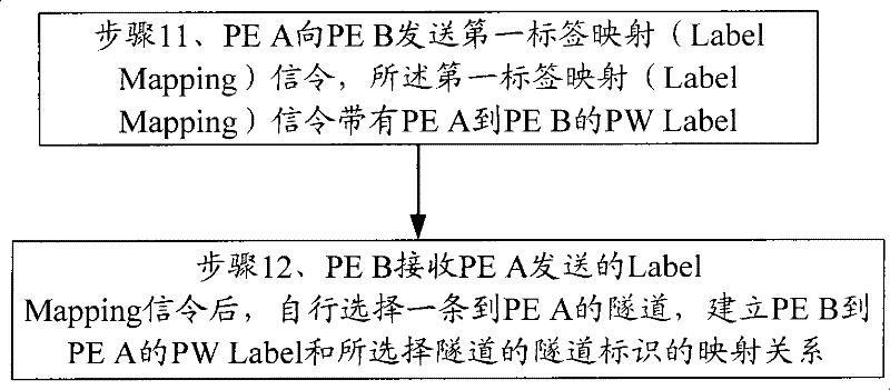
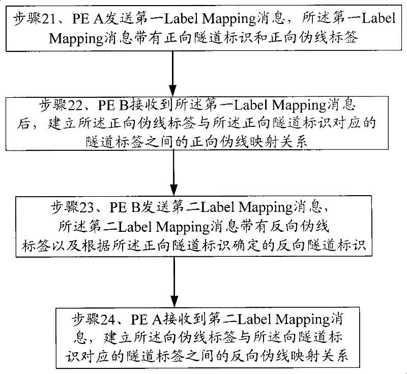
[0030] Example 1: The specific implementation of the present invention provides a method for establishing pseudo wire mapping. For the convenience of description, set the first node as PE A and the second node as PE B. The specific steps of the method are as follows: figure 2 Shown, including:
[0031] Step 21: PE A sends a first Label Mapping message, where the first Label Mapping message carries a forward tunnel identifier and a forward pseudowire label;
[0032] The method for implementing the forward tunnel identifier in the first Label Mapping message in this step can be to add a tunnel identifier field to the Pseudowire identifier Type (Length, Value, PWid TLV) object of the Label Mapping message. The tunnel identifier field is used to carry the forward tunnel identifier. Of course, the tunnel identifier can also be loaded in other positions of the first Label Mapping message. The specific embodiment of the present invention is not limited to the specific position of the tunn...
Embodiment 2
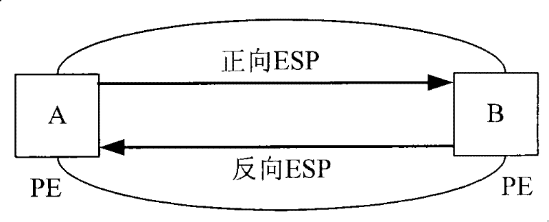
[0042] Embodiment 2: The specific implementation of the present invention provides a method for establishing pseudo wire mapping. The technical scenario of this embodiment is that the pseudo wire mapping is established in PBB-TE in this embodiment. The tunnel label is ESPID, and the pseudo wire The label is I-SID. In this embodiment, the pseudo wire mapping in the direction from PE A to PE B is set as forward pseudo wire mapping, of course, it can also be set as reverse pseudo wire mapping. PE A and PE B in this embodiment The connection is like image 3 Shown. The method described in Example 2 is Figure 4 As shown, including the following operations:
[0043] Step 41: PE A sends a first LabelMapping message with a forward ESP ID and a forward I-SID to PE B;
[0044] The forward ESP ID in the above steps can be specifically, , Where MAC_A and MAC_B are the MAC addresses of nodes PE A and PE B, respectively, and B-VID1 is a VLAN identifier. The I-SID in this step is the pseudowi...
Embodiment 3
[0051] Embodiment 3: The specific implementation of the present invention provides a method for establishing pseudowire mapping. The technical scenario of this embodiment is that the pseudowire establishment in this embodiment is between PE A and PE in an MPLS / T-MPLS network. The connection between PE A and PE B in the MPLS network is established between B, Figure 5 As shown, the tunnel identifier is LSP ID, the pseudowire label is MPLS PW Label, and the pseudowire mapping from PE A to PE B is defined as a forward pseudowire mapping. For MPLS / T-MPLS networks, when the tunnel identifier is LSP ID, a bidirectional LSP will have a corresponding LSP ID in the management or control plane. At this time, the forward LSP ID and the reverse LSP ID are actually the same LSP ID. That is, the forward tunnel identifier at this time is the same as the reverse tunnel identifier corresponding to the tunnel identifier. However, for the convenience of description, this embodiment still divides t...
PUM
 Abstract
Description
Claims
Application Information
 - R&D
- Intellectual Property
- Life Sciences
- Materials
- Tech Scout
- Unparalleled Data Quality
- Higher Quality Content
- 60% Fewer Hallucinations
Browse by: Latest US Patents, China's latest patents, Technical Efficacy Thesaurus, Application Domain, Technology Topic, Popular Technical Reports.
© 2025 PatSnap. All rights reserved.Legal|Privacy policy|Modern Slavery Act Transparency Statement|Sitemap|About US| Contact US: help@patsnap.com