A monitor terminal device for remote control

A technology for remote control and monitoring of terminals, used in telemetry/remote control selection devices, lighting devices, selection devices, etc.

Inactive Publication Date: 2014-01-29
TOSHIBA LIGHTING & TECH CORP
View PDF5 Cites 0 Cited by
  • Summary
  • Abstract
  • Description
  • Claims
  • Application Information

AI Technical Summary

Problems solved by technology

[0011] In addition, it is considered that a switch using a touch panel may have the following problem, that is, it is easy to mistakenly detect an adjacent operation part and illuminate an illuminating area that does not need to be illuminated. control

Method used


Image

  • A monitor terminal device for remote control
  • A monitor terminal device for remote control
  • A monitor terminal device for remote control

Examples


Embodiment Construction

[0098] In order to further explain the technical means and effects of the present invention to achieve the intended purpose of the invention, the specific implementation, structure and characteristics of the monitoring terminal device for remote control proposed according to the present invention will be described below in conjunction with the accompanying drawings and preferred embodiments. and its effects are described in detail.

[0099] Hereinafter, embodiments of the present invention will be described with reference to the drawings.

[0100] (first embodiment)

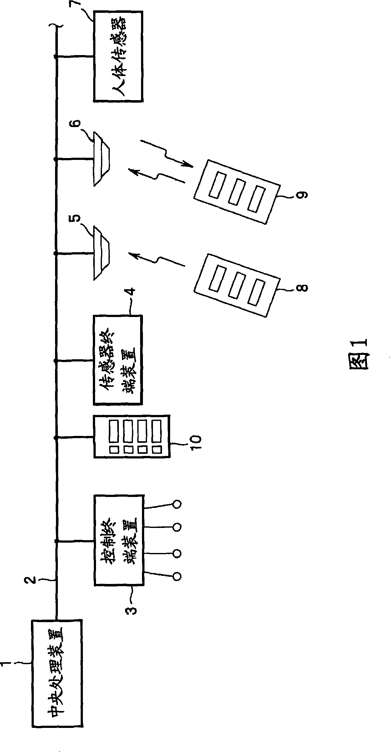
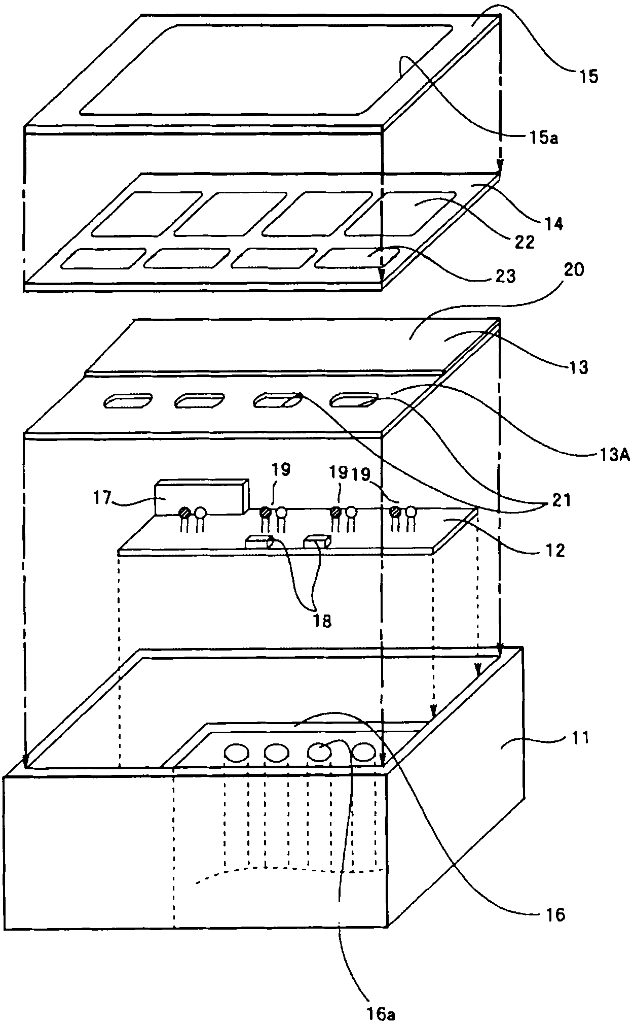
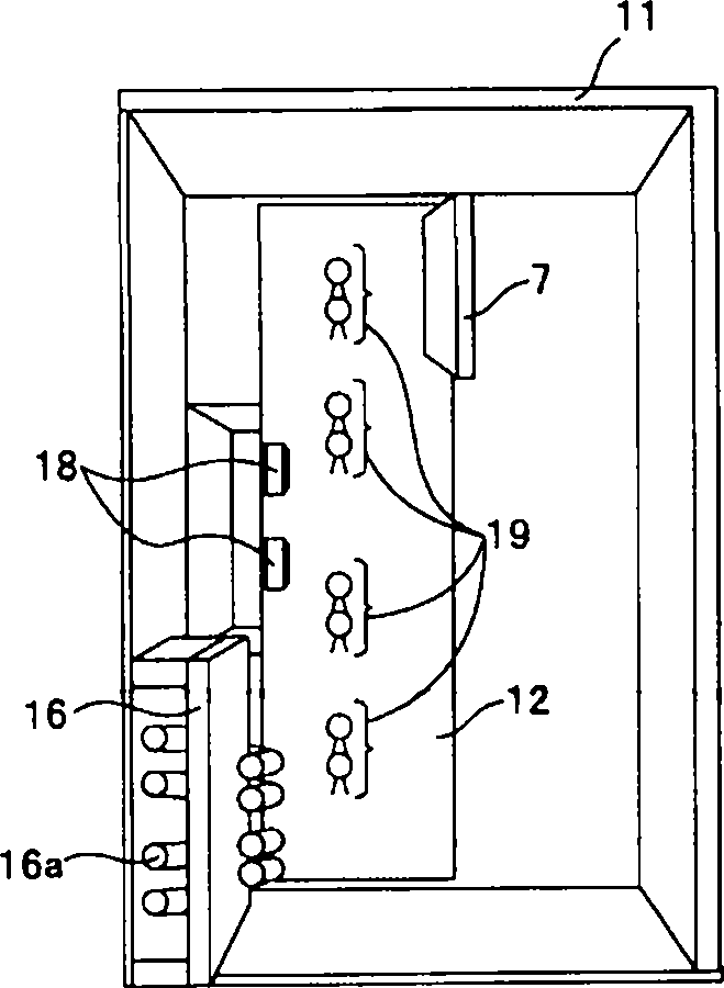
[0101] Figure 1 to Figure 13 It is the first embodiment of the monitoring terminal device for remote control of the present invention, figure 1 It is an overall configuration diagram of a remote monitoring and control system with a monitoring terminal device for remote control, figure 2 It is an exploded perspective view illustrating the configuration of a monitoring terminal device for remote control, Fi...


PUM


Abstract

PURPOSE: A monitoring terminal for remote control is provided to correct a reverse value so as to be optimized, automatically, although noises are generated according to the installation environment. CONSTITUTION: A monitoring terminal for remote control comprises a case body(11), an operation panel(14), a touch substrate(13) and a transmission unit(12). The operation panel includes a plurality of manipulation units(22). The touch substrate is arranged on the case body and in the rear side of the operation panel into which a plurality of touch manipulation parts(20) are inserted. The transmission unit is electrically connected to the touch substrate to output a manipulation signal when the pressing of the touch manipulation parts is detected.

Description

technical field [0001] The present invention relates to a monitor terminal device for remote control that outputs an operation signal to, for example, a plurality of lighting fixtures arranged on a ceiling surface in a building for remote control. Background technique [0002] In general, for example, a plurality of lighting fixtures installed on a ceiling in a building output an operation signal by manual operation of a monitoring terminal device for remote control that can be operated remotely, and the user who receives the operation signal Central processing unit to control on / off. [0003] Such a monitoring terminal device for remote control comprises a main part comprising a case main body mounted on a fixing bracket provided on a wall or the like, and an operation part for remote operation mounted on the case main body. [0004] The operation unit is formed corresponding to the operation mode for remotely operating predetermined lighting fixtures among the plurality o...

Claims


Application Information

Patent Timeline
Patent Type & Authority Patents(China)
IPC IPC(8): H05B37/02H04Q9/00
CPCY02B20/42Y02B20/40F21V23/0435H01H2231/032H05B47/16H05B47/175
Inventor 石田幸男森本康司
Owner TOSHIBA LIGHTING & TECH CORP
Why Eureka
Try Eureka