Method and equipment for detecting sealing deficiencies in drainage and vent systems for buildings

A ventilation system and drainage system technology, applied in the water supply pipeline system, fluid tightness test, and by detecting the appearance of fluid at the leakage point, etc., it can solve the problems of waste water pushing in, breaking fast water seals, etc.

Inactive Publication Date: 2009-10-07
HERIOT WATT UNIV
View PDF0 Cites 5 Cited by
  • Summary
  • Abstract
  • Description
  • Claims
  • Application Information

AI Technical Summary

Problems solved by technology

[0007] On the other hand, if the air pressure in the drain suddenly becomes higher than the ambient air pressure, this positive transient can cause waste water (and exhaust air) to be pushed into the facility, breaking water seals and causing dire sanitation and health hazards ACCIDENT

Method used


Image

  • Method and equipment for detecting sealing deficiencies in drainage and vent systems for buildings
  • Method and equipment for detecting sealing deficiencies in drainage and vent systems for buildings
  • Method and equipment for detecting sealing deficiencies in drainage and vent systems for buildings

Examples


Embodiment Construction

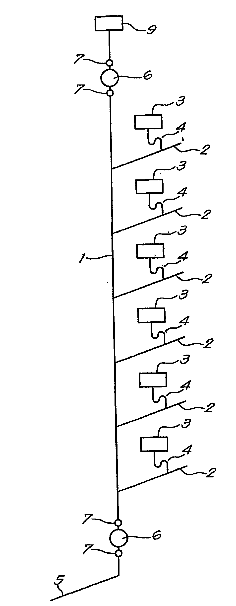
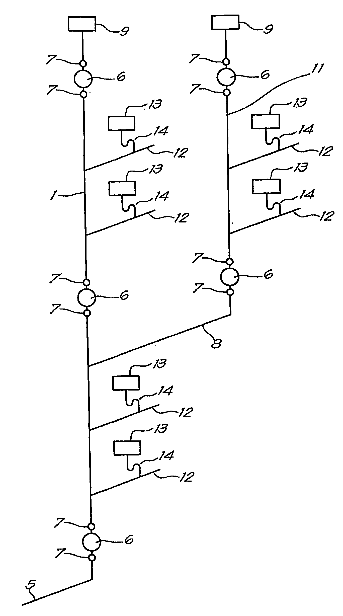
[0019] Such as figure 1 As shown, a drainage system of a multi-storey building is shown in a simplified manner, comprising a vertical riser discharge pipe 1, to which a series of drain pipes 2 from each floor are connected, and discharge sources from each floor 3 can leak into it. The discharge source may be any sanitary fixture such as a toilet, floor drain, sink, shower, bidet, and the like.

[0020] Between each discharge source 3 and the drain pipe 2, the pipeline generally includes a U-shaped water trap 4 (water trap) or the like.

[0021] Liquid and / or liquid / solid effluents from discharge sources 3 are conveyed through their respective dehydrators 4 to drains 2 and then through vertical standpipes 1 finally into drains 5 .

[0022] The complete system is vented to the surrounding atmosphere by means of an air admission valve 9, which is generally arranged at the uppermost end of the standpipe 1, but may also be contained in the housing of the water seal. As already e...


PUM


Abstract

The method comprises the following steps - introducing a low amplitude air pressure transient into the drainage and vent system of a building in order to propagate a pressure wave from a fitting (6) into a stack (1) and the network of the drainage system; - recording the passage of said transient by means of an air pressure transducer (7) located near the fitting (6) or introduction area of the transient; - recording the successive pressure reflections of the transient from each drain pipe (2) of the network of the drainage system; - establishing a pressure versus time signature recorded by the pressure transducer (7) and sending those signals to a central data acquisition system; - the pressure transient is propagated throughout the network at an acoustic velocity and is reflected by each and every pipe termination of the network so as to establish a characteristic reflection coefficient for each pipe termination; - said characteristic reflection coefficient is compared with testing results performed initially in a perfect network with no dry trap defects or leakage's and in case a different signature of the pressure trace is recorded, the point of diversion will be determined at the time at which the reflection from the altered pipe end termination arrives at the air pressure transducer so that the comparison of this defect trace with the stored defect free signature yields that time and, as the wave speed is known, the determination of the distance from the pressure transducer to the defective trap or seal.

Description

technical field [0001] The present invention relates to a method and apparatus for detecting seal defects, such as defective water traps and other seal failure defects, within building drainage and ventilation systems. Background technique [0002] The purpose of drainage systems installed in buildings is to direct waste water from sanitary facilities such as toilets, washbasins, tubs etc. into drains which are usually located below the ground level of the building. In a multi-storey building, the drainage system has at least one vertical standpipe extending through the floor of each floor and branch pipes leading waste water from each sanitary facility on each floor into the vertical standpipe by means of connections. Standpipes and / or branch pipes or even each specific sanitary facility may be provided with air admission valves or other suitable ventilation arrangements, and / or positive air pressure attenuation devices. [0003] A water trap or water seal is generally use...

Claims


Application Information

Patent Timeline
Patent Type & Authority Applications(China)
IPC IPC(8): E03C1/122G01M3/24G01M3/28
CPCG01M3/243G01M3/2815E03B7/003G01M3/2807E03C1/122G01M3/24G01M3/28F16L55/00
Inventor J·斯沃菲尔德D·坎普贝尔L·杰克M·戈姆利
Owner HERIOT WATT UNIV
Why Eureka
Try Eureka