Improved carbon dioxide drive oil production method

A carbon dioxide, oil reservoir technology, applied in the fields of fluid production, earthwork drilling, wellbore/well components, etc., can solve the problems of low displacement efficiency and less crude oil, etc.

Active Publication Date: 2009-10-14
PETROCHINA CO LTD
View PDF2 Cites 17 Cited by
  • Summary
  • Abstract
  • Description
  • Claims
  • Application Information

AI Technical Summary

Problems solved by technology

However, once carbon dioxide is produced from the production well, it means that the carbon dioxide has channeled, forming a channel for carbon dioxide in the oil layer, and the carbon dioxide is produced from the production well through the channel from the injection well, carrying very little crude oil, and the displacement efficiency is reduced

Method used


Image

  • Improved carbon dioxide drive oil production method
  • Improved carbon dioxide drive oil production method
  • Improved carbon dioxide drive oil production method

Examples


Embodiment 1

[0034] Embodiment 1: Taking a block with a reservoir pressure of 10 MPa as an example to carry out an improved carbon dioxide flooding recovery process, the detailed description will be given.

[0035] In a block of an oilfield, the depth of the oil layer is 1800 meters, and the thickness of the oil layer is 10 meters, and the depletion production has been carried out. Reservoir pressure is 10 MPa after depleted production. A decision was made to develop improved CO2 flooding.

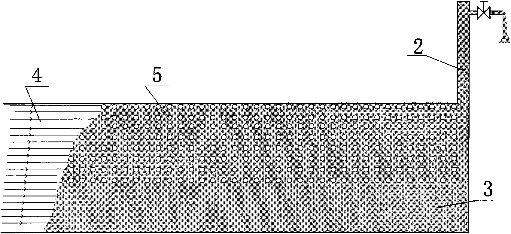
[0036] refer to Figure 4 . Step 1: Improve the well pattern in the carbon dioxide flooding area, using a nine-point well pattern, with the gas injection well 1 in the middle, surrounded by 8 production wells 2, and the 8 production wells 2 are arranged in a rectangle. The gas injection well 1 is 100-200 meters away from the near production well 2, and 140-280 meters away from the far production well 2. In the present embodiment, there are 150 meters away from the nearer production well 2, and 200 ...

Embodiment 2

[0042] Embodiment 2: Taking a block with an oil reservoir pressure of 25 MPa as an example to carry out an improved carbon dioxide flooding recovery process, the detailed description will be given.

[0043] In a block of an oilfield, the depth of the oil layer is 3000 meters, and the thickness of the oil layer is 18 meters, and the depletion production has been carried out. Reservoir pressure is 25 MPa after depleted production. A decision was made to develop improved CO2 flooding.

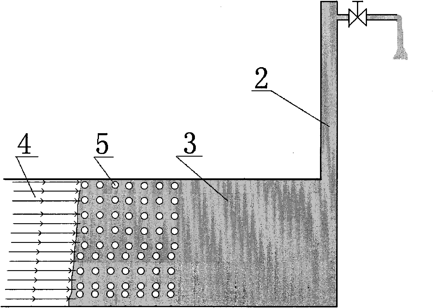
[0044] refer to image 3 . Step 1: Improve the well pattern in the carbon dioxide flooding area, adopt a nine-point well pattern, the gas injection well is in the middle, and there are 8 production wells around it. The distance between the production well 2 and the gas injection well 1 is 150 meters, and the distance between the production well 2 and the gas injection well 1 is 200 meters. . The gas injection well is connected with carbon dioxide gas injection equipment, and the production well ...


PUM


Abstract

The invention relates to an improved carbon dioxide drive oil production method which is applied to oil production in oil fields. The invention is characterized in that A. carbon dioxide is injected into a gas injection well; and B. under the condition of continuous injection of carbon dioxide, peripheral production wells are opened for production and closed discontinuously. In the period of closing the well, the pressure of an oil pool at the periphery of the gas injection well raises, and when the pressure raises to a certain extent, the production wells are opened for production; with the production of the opened production wells, the pressure of the oil pool at the periphery of the gas injection well decreases and when the pressure decreases to a certain extent, the production wells are closed; and the above steps are repeatedly circulated. The method has the effects that the drive oil effect can be improved and the recovery ratio of the oil pool is improved; and when the pressureraises, part of carbon dioxide can be dissolved into the crude oil; when the pressure decreases, the carbon dioxide can be separated from the crude oil so as to form small bubbles and the volume of the crude oil is obviously expanded compared with the volume of the crude oil when the carbon dioxide is not separated. As the carbon dioxide is injected continuously, the expanded crude oil expands todownstream, thus driving the downstream crude oil to flow to the production wells.

Description

technical field [0001] The invention relates to the technical field of oil recovery in oil fields, in particular to a method for producing crude oil by injecting carbon dioxide, which is an oil recovery method for improving the recovery rate and development effect of oil reservoirs. Background technique [0002] At present, the conventional carbon dioxide injection technology is to continuously inject carbon dioxide from the gas injection well into the oil reservoir, and use carbon dioxide to drive crude oil to flow to the production wells around the gas injection well, and the production wells produce continuously. However, once carbon dioxide is produced from the production well, it means that the carbon dioxide has channeled and a channel of carbon dioxide is formed in the oil layer. The carbon dioxide is produced from the injection well through the channel and from the production well, carrying very little crude oil, and the displacement efficiency is reduced. [0003] P...

Claims


Application Information

Patent Timeline
Patent Type & Authority Applications(China)
IPC IPC(8): E21B43/16E21B43/22E21B43/24
Inventor 陈亚平
Owner PETROCHINA CO LTD
Why Eureka
Try Eureka