Electromagnetic induction gyroscope

A technology of electromagnetic induction and gyroscope, applied in the field of gyroscope, can solve the problems of high cost, complex configuration, low precision, etc.

Active Publication Date: 2009-10-14
BEIJING TIANHAI HANGXING TECH
View PDF0 Cites 4 Cited by
  • Summary
  • Abstract
  • Description
  • Claims
  • Application Information

AI Technical Summary

Problems solved by technology

Mechanical gyroscopes have high precision and good stability, but poor impact resistance and large volume and weight
Piezoelectric crystal gyroscopes are small in size but low in accuracy and stability
Laser...

Method used


Image

  • Electromagnetic induction gyroscope
  • Electromagnetic induction gyroscope
  • Electromagnetic induction gyroscope

Examples


Embodiment 1

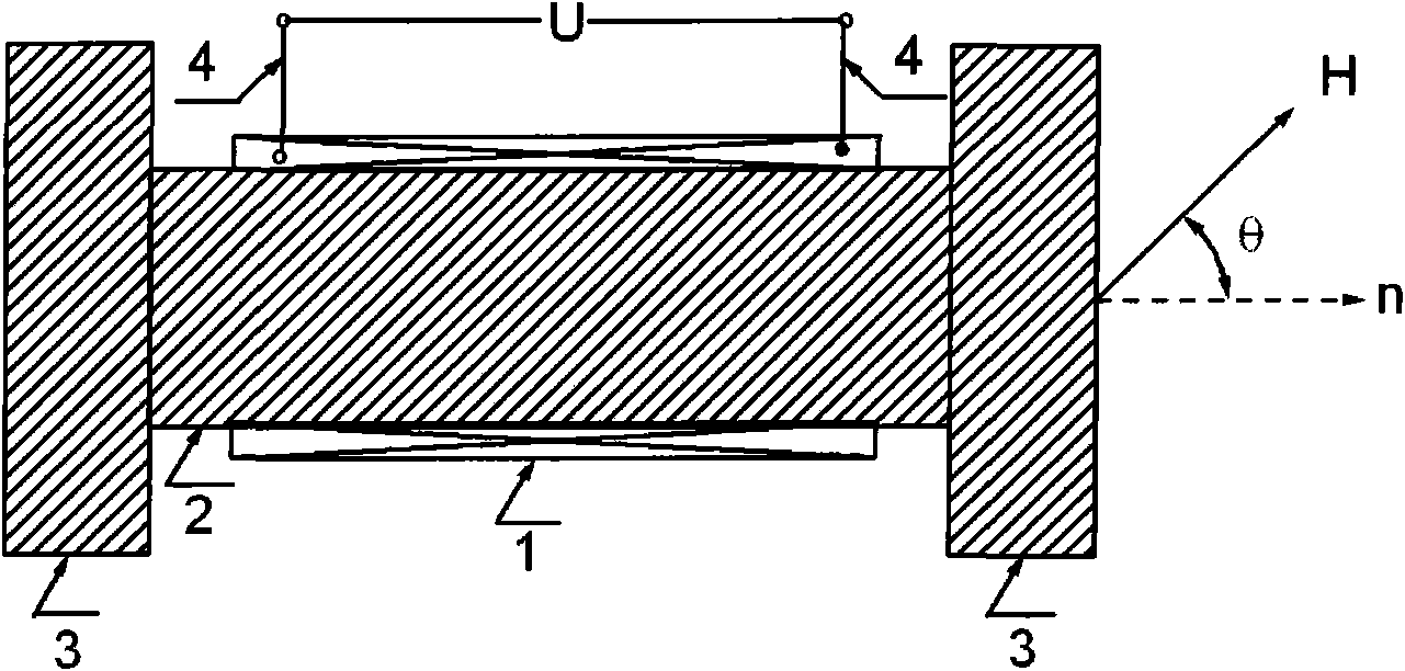
[0013] Example 1, such as figure 1 As shown, this is a one-dimensional electromagnetic induction gyroscope. The gyroscope is composed of a coil 1, a magnetic guide shaft 2, and a magnetic detection panel 3. The coil 1 is wound around the outer circumference of the magnetic guide shaft 2, and the two ends of the magnetic guide shaft 2 are connected with magnetic The detection panel 3 and the induced electromotive force signal generated by the coil 1 are drawn out by the wire 4 .

Embodiment 2

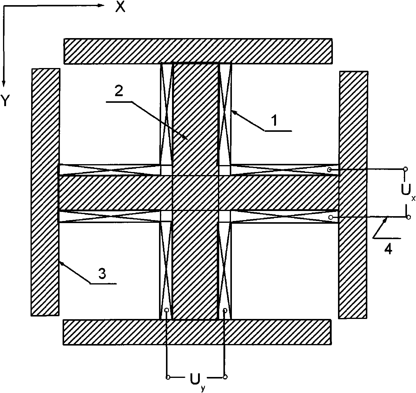
[0014] Example 2, such as figure 2 As shown, this is a two-dimensional electromagnetic induction gyroscope. The gyroscope is composed of two sets of coils 1, the magnetic guide shaft 2, and the magnetic detection panel 3. The coil 1 is wound around the outer circumference of the magnetic guide shaft 2, and the two ends of the magnetic guide shaft 2 are connected. There are magnetic detection panels 3, and the adjacent magnetic detection panels 3 cannot be connected magnetically. The two magnetic guide shafts 2 are respectively fixed in two directions perpendicular to each other.

Embodiment 3

[0015] Example 3, such as Figure 3-5 As shown, this is a three-dimensional electromagnetic induction gyroscope. The gyroscope is composed of three sets of coils 1, magnetic guide shaft 2, and magnetic detection panel 3. The coil 1 is wound around the outer circumference of the magnetic guide shaft 2, and the two ends of the magnetic guide shaft 2 are connected with The magnetic detection panels 3 and adjacent magnetic detection panels 3 cannot be connected magnetically. The two magnetic guide shafts 2 are respectively fixed in three directions perpendicular to each other. The induced electromotive force signal generated by the coil 1 is drawn out by the wire 4 .

[0016] Principle of the present invention is as follows:

[0017] When the gyroscope moves in the magnetic field, the included angle between the normal direction n of the magnetic detection panel 3 made of ferromagnetic material and the magnetic field H at a certain moment is θ, and the area of ​​the magnetic detect...


PUM


Abstract

The invention relates to an electromagnetic induction gyroscope, comprising a coil, a magnetic guide shaft, a magnetic detection panel; wherein, the coil winds on the magnetic guide shaft; the magnetic guide shaft is connected with the magnetic detection panel; when the gyroscope moves in a geomagnetic field or other external magnetic fields, magnetic flux of the coil changes, so that induced electromotive force is generated at the two ends of the coil. The induced electromotive force and the coil axial directon in the gyroscope are related to the included angle and the rotation speed of the field direction. The gyroscope based on electromagnetic induction is a passive whirly monitoring sensor, the gyroscope has the characteristics of simple and stable structure, small volume, good impact resistance capacity, stable temperature property and convenient application, thus being widely applied to the angular velocity measurement and magnetic density measurement of whirling objects.

Description

technical field [0001] The invention relates to a gyroscope based on electromagnetic induction. The present invention has special applications in the angular velocity monitoring of space vehicles and rotating objects, such as the navigation of aircraft and missiles, but can also be widely used in the angular velocity measurement of other rotating objects, such as the movement and rotation control of manipulators, and the measurement of magnetic field strength. Background technique [0002] Gyroscope is a kind of rotation monitoring sensor, which has a wide range of applications in engineering technology and scientific research, such as aircraft navigation, manipulator movement and rotation control, etc. At present, the commonly used gyroscopes include mechanical gyroscopes, piezoelectric crystal gyroscopes, laser gyroscopes and fiber optic gyroscopes. Mechanical gyroscopes have high precision and good stability, but poor impact resistance and large volume and weight. Piezo...

Claims


Application Information

Patent Timeline
IPC IPC(8): G01C19/00G01C19/04
Inventor 谭成忠
Owner BEIJING TIANHAI HANGXING TECH
Why Eureka
Try Eureka