Glass sheet defect detection device, glass sheet manufacturing method, glass sheet, glass sheet quality judging device, and glass sheet inspection method

A defect detection and manufacturing method technology, applied in measuring devices, measurement/testing in the manufacturing process, using optical devices, etc., can solve the problem of high manufacturing cost and achieve the effect of high detection capability

Active Publication Date: 2009-10-14
NIPPON ELECTRIC GLASS CO LTD
View PDF2 Cites 23 Cited by
  • Summary
  • Abstract
  • Description
  • Claims
  • Application Information

AI Technical Summary

Problems solved by technology

On the other hand, the manufacturing cost cannot be higher than before due to factors such as extended inspection time and become a high price.

Method used


Image

  • Glass sheet defect detection device, glass sheet manufacturing method, glass sheet, glass sheet quality judging device, and glass sheet inspection method
  • Glass sheet defect detection device, glass sheet manufacturing method, glass sheet, glass sheet quality judging device, and glass sheet inspection method
  • Glass sheet defect detection device, glass sheet manufacturing method, glass sheet, glass sheet quality judging device, and glass sheet inspection method

Examples


Embodiment 1

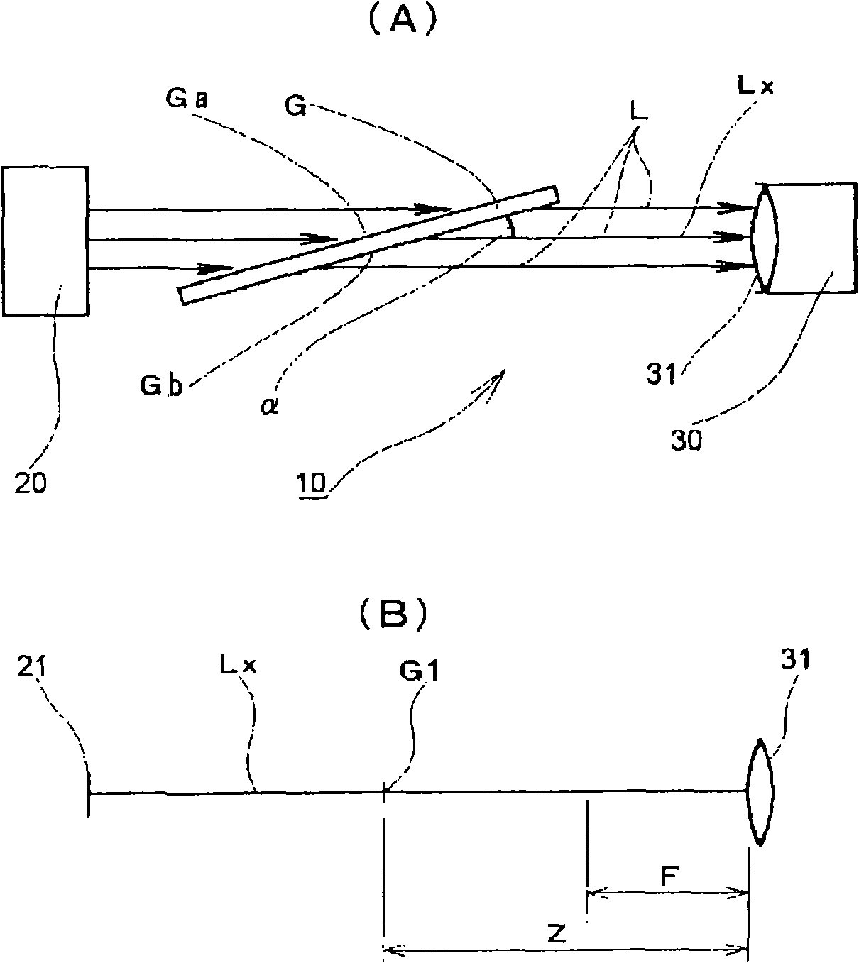
[0089] figure 2 (A) and (B) schematically show the glass plate defect detection apparatus 10 of Example 1. FIG. This glass plate defect detection apparatus 10 is equipped with the light source 20 and the light receiving device 30 arrange|positioned in the opposing position which sandwiches the glass plate G. The glass plate G has light-transmitting surfaces Ga, Gb opposite to its thickness direction, with the light-transmitting surfaces Ga, Gb relative to the optical axis Lx of the optical system of the glass plate defect detection device 10 (connected to form from the light source 20 to the light receiving device 30 The center line of a series of optical elements of the optical system) is arranged between the light source 20 and the light receiving device 30 in such a manner that it is inclined at a predetermined angle α. In addition, the light receiving device 30 and the glass plate G are on the optical axis Lx so that the focal distance F of the lens system 31 of the ligh...

Embodiment 2

[0114] Next, refer to Image 6 , the glass plate defect detection device 11 of the second embodiment will be described in detail. This glass plate defect detection apparatus 11 is comprised, for example to save space and to measure continuously the thin glass plate G of 1500 mm in width and 0.65 mm in thickness mounted in a TFT liquid crystal display device. Image 6 The main components of the glass sheet defect detection device 11 are schematically shown, showing a state in which the glass sheet G is continuously drawn downward by heat-resistant rollers (not shown) after being formed in a glass melting furnace from above to below. W in the figure shows the moving direction of the glass plate G.

[0115] This glass plate defect detection apparatus 11 is equipped with the light source 20 arrange|positioned at the position which pinches the glass plate G, the light receiving device 30a, and the reflection mirror 40. For example, a metal halide lamp is used as the light source ...

Embodiment 3

[0119] also, Figure 7 A schematic diagram showing another configuration of a glass plate defect detection device. In this glass plate defect detection device, on the optical axis Lx, the distance from the light source 20 to the position G1 of the glass plate G is set to 1000 mm, and the distance from the position G1 of the glass plate G to the solid-state imaging element of the light receiving device 30a is set to 1000 mm. Set as 1000mm. The focal length of the lens system of the light receiving device 30a is 700 mm. Therefore, on the optical axis Lx, the focal length of the lens system of the light receiving device 30a is 700mm smaller than the distance from the light receiving device 30a to the position G1 of the glass plate G of 1000mm. In addition, the angle α formed by the light-transmitting surfaces Ga, Gb of the glass plate G and the optical axis Lx is 20°.

[0120] This glass sheet defect detection device is configured to perform measurement while moving the cut gl...


PUM

PropertyMeasurementUnit
thicknessaaaaaaaaaa

Abstract

The invention provides a glass sheet defect detection device to rapidly, effectively, and accurately detect various defects generated inside or on the surface of a glass sheet. The glass sheet defect detection device (10) includes a light source (20) and a light reception device (30) which are arranged at opposite positions so as to sandwich a glass sheet (G). The glass sheet (G) has light transmission surfaces (Ga, Gb) to oppose each other in the thickness direction. The glass sheet (G) is arranged between the light source (20) and the light reception device (30) so that the light transmission surfaces (Ga, Gb) are inclined against a light axis (Lx) of an optical system of the glass sheet defect detection device (10) by a predetermined angle a. Moreover, the light reception device (30) and the glass sheet (G) are arranged with such a positional relationship that a focal distance (F) of a lens system (31) of the light reception device (30) is smaller than a distance (Z) between the light reception element of the light reception device (30) and the glass sheet (G).

Description

technical field [0001] The present invention relates to a defect detection device for detecting defects in a glass plate formed by molten glass, especially a glass plate mounted on a liquid crystal display device or a plasma display, a method of manufacturing a glass plate using the defect detection device, and a method for manufacturing a glass plate using the defect detection device. The obtained glass plate product, and a good / bad judging device for evaluating defects of the glass plate and making a good / bad judgment. Background technique [0002] Along with the remarkable development of display device technologies, technologies related to image display devices of various types, such as liquid crystal displays and plasma displays, have also been greatly developed. In particular, large-scale and high-definition image display devices and the like are undergoing profound technical innovations in order to reduce their manufacturing costs and improve image quality. Glass plat...

Claims


Application Information

Patent Timeline
Patent Type & Authority Applications(China)
IPC IPC(8): G01N21/958G01M11/00G01B11/30G02F1/13G02F1/1333H01J9/42G01N21/896
CPCG02F2001/133302G01N21/896G01M11/081C09K2323/033G02F1/133302G01B11/30G01M11/00G01N21/958G02F1/13
Inventor 水津秀美西村康弘岩田正和
Owner NIPPON ELECTRIC GLASS CO LTD
Why Eureka
Try Eureka