Vacuum cleaner and control method thereof

A technology of a vacuum cleaner and a control method, applied in the directions of vacuum cleaners, suction filters, cleaning equipment, etc., can solve problems such as inconvenience of use and occupying too much space, and achieve the effects of preventing dust scattering, reducing damage, and improving reliability.

Inactive Publication Date: 2009-10-21
LG ELECTRONICS (TIANJIN) APPLIANCES CO LTD
View PDF0 Cites 10 Cited by
  • Summary
  • Abstract
  • Description
  • Claims
  • Application Information

AI Technical Summary

Problems solved by technology

[0009] According to the dust collecting device in the above-mentioned prior art, since the dust stored in the dust storage part occupies an excessively large space relative to its weight, in order to maintain the dust collecting performance of the vacuum cleaner, it is necessary to frequently empty the dust in the dust collecting device, resulting in inconvenience in use

Method used


Image

  • Vacuum cleaner and control method thereof
  • Vacuum cleaner and control method thereof
  • Vacuum cleaner and control method thereof

Examples


Embodiment Construction

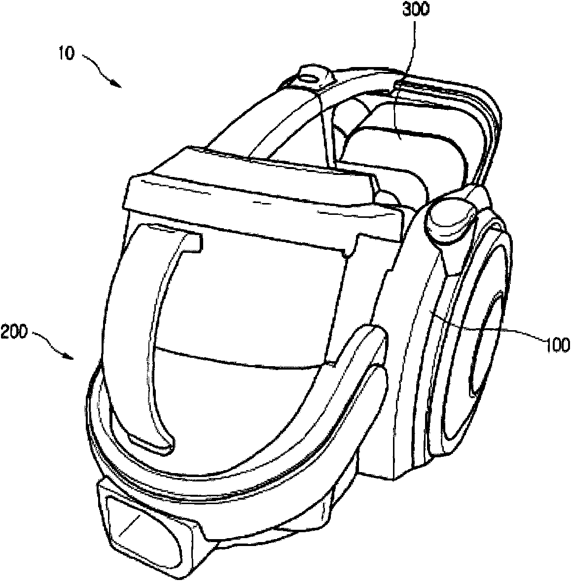
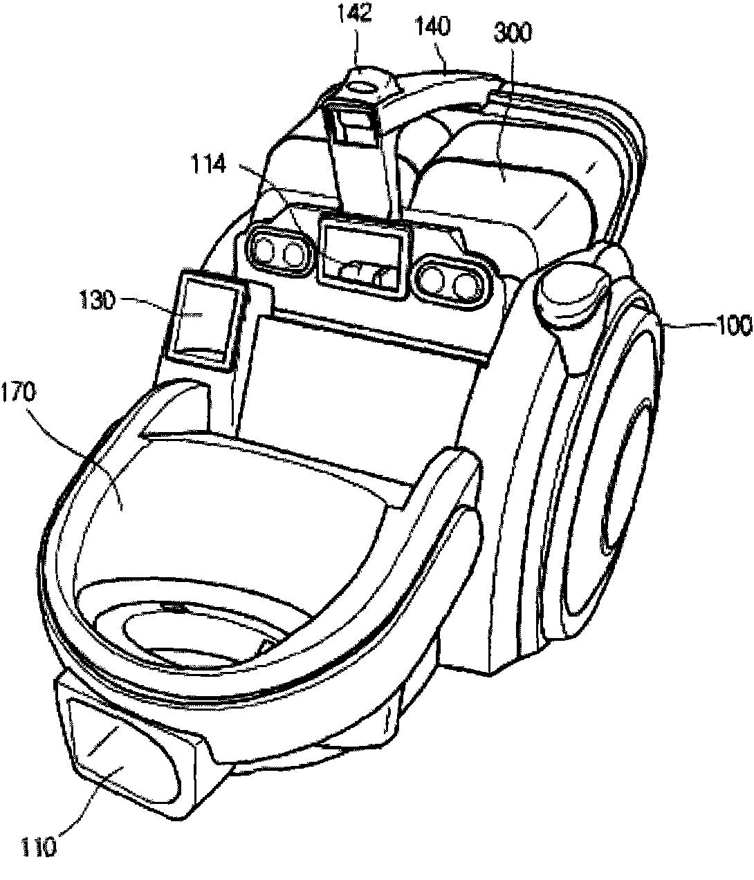
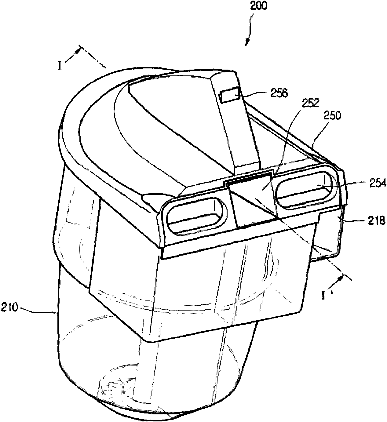
[0040] Hereinafter, specific embodiments of the present invention will be described with reference to the drawings. figure 1 Is a perspective view of the vacuum cleaner of the present invention, figure 2 Yes figure 1 A perspective view of the vacuum cleaner in the state of separating the dust collection device, image 3 It is a perspective view of the vacuum cleaner dust collecting device of the present invention.

[0041] Reference Figure 1 to Figure 3 , The vacuum cleaner 10 of the present invention includes: a vacuum cleaner body 100, which is provided with a motor (not shown in the figure) for generating suction; a dust separation device, which is used to separate the vacuum cleaner body 100 inhaled in the air dust.

[0042] In addition, although not shown, the vacuum cleaner 10 also includes: a suction nozzle, which is used to suck air containing dust; and a connecting pipe, which is used to connect the suction nozzle to the vacuum cleaner body 100.

[0043] In the vacuum...


PUM


Abstract

The invention relates to a vacuum cleaner which comprises a cleaner body where a dust collecting device installing part is formed, a dust collecting device arranged in an assembly and disassembly manner and on which a dust storage part is formed, compressing components used for compressing the dust stored in the dust storage part, a driving device used for driving the compressing components, a controlling part used for controlling the driving device, a misoperation detecting part for detecting whether the compressing components is misoperated and a display part for displaying the misoperation signal of the compressing components outside through the controlling part. Due to the adoption of the vacuum cleaner and the control method thereof, the dust stored inside the dust collecting device can be compressed through the pair of the compressing components, the volume is minimized, the maximum dust collection capacity of the dust stored inside the dust collecting device can be realized, the user does not need to frequently clean the dust stored inside the dust collecting device and can use the vacuum cleaner conveniently.

Description

Technical field [0001] The present invention relates to a vacuum cleaner, and in particular, to a vacuum cleaner that maximizes the dust collection capacity of a dust collection device and a control method thereof. Background technique [0002] Generally speaking, a vacuum cleaner is a device that uses vacuum pressure generated by a vacuum motor installed inside the body to suck air containing dust, and then filter the sucked dust inside the body. [0003] The vacuum cleaner includes: a suction nozzle for sucking air containing dust; a vacuum cleaner body, which is connected to the suction nozzle; a telescopic tube, which guides the air sucked by the suction nozzle to the direction of the vacuum cleaner body; The air is guided into the body of the vacuum cleaner. [0004] Among them, a nozzle suction opening of a certain size is formed at the bottom of the suction nozzle, so that air containing dust accumulated on the ground can be sucked in. [0005] A drive unit is provided ins...

Claims


Application Information

Patent Timeline
Patent Type & Authority Applications(China)
IPC IPC(8): A47L5/12A47L9/10A47L9/19
Inventor 河建镐徐真旭尹昌虎金镇泳李昌勋
Owner LG ELECTRONICS (TIANJIN) APPLIANCES CO LTD
Why Eureka
Try Eureka