
Machine tool chip removal device

A technology of chip removal device and machine tool, which is applied to metal processing machinery parts, maintenance and safety accessories, metal processing equipment, etc. Attached, to avoid the effect of flying

Inactive Publication Date: 2020-11-17
江苏巨麦机床科技有限公司
View PDF6 Cites 0 Cited by
  • Summary
  • Abstract
  • Description
  • Claims
  • Application Information

AI Technical Summary

Problems solved by technology

The existing chip removal machine is horizontal and linear, and the inclination angle cannot be adjusted to speed up the passage of waste chips. The waste chips adhere to the conveyor belt, and the height of the waste chip box cannot be adjusted, causing the waste chips to splash out

Method used


Image

  • Machine tool chip removal device
  • Machine tool chip removal device

Examples


Embodiment Construction

[0025] The following will clearly and completely describe the technical solutions in the embodiments of the present invention with reference to the accompanying drawings in the embodiments of the present invention. Obviously, the described embodiments are only some of the embodiments of the present invention, not all of them. Based on the embodiments of the present invention, all other embodiments obtained by persons of ordinary skill in the art without making creative efforts belong to the protection scope of the present invention.

[0026] In the description of the present invention, it should be noted that the terms "upper", "lower", "inner", "outer", "front end", "rear end", "both ends", "one end", "another end" The orientation or positional relationship indicated by etc. is based on the orientation or positional relationship shown in the drawings, and is only for the convenience of describing the present invention and simplifying the description, rather than indicating or ...


PUM


Abstract

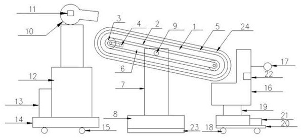
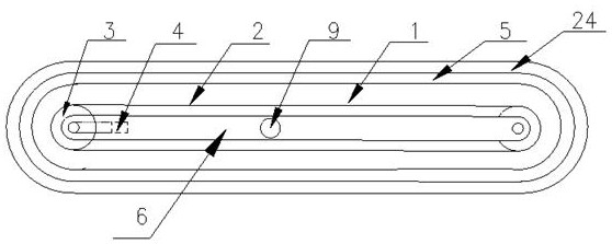
The invention discloses a machine tool chip removal device which comprises a conveying structure, an air supply structure and a chip collection structure. The air supply structure and the chip collection structure are arranged at the two ends of the conveying structure, the conveying structure can adjust the inclination angle of the conveying structure through a hinge structure to achieve the speed of waste chips passing through a conveying belt, and the air supply structure can conduct height adjustment according to the inclination angle of the conveying structure, so that the waste chips ona flat plate can be rapidly and thoroughly discharged; the height of the chip collection structure can be adjusted according to the inclination of the conveying structure, so that it is guaranteed that the waste chips accurately fall into the chip collection structure; a damping structure is arranged below the base, so that vibration of the whole body due to the lifting process and adjusting of the hinge structure is avoided; baffles are arranged at the two sides of the flat plate, so that flying of the waste chips is avoided when a draught fan supplies air; and zinc coatings are arranged at the upper surface of the flat plate and in the chip collection box, so that adhesion of waste chips to the flat plate and the chip collection box is reduced.

Description

technical field [0001] The invention relates to the technical field of machine tools, in particular to a machine tool chip removal device. Background technique [0002] The chip conveyor is a machine that is mainly used to collect various metal and non-metal waste chips generated by the machine, and transfer the waste chips to the collection vehicle. The existing chip conveyor is horizontal and linear, and the inclination angle cannot be adjusted to speed up the passage of waste chips. The waste chips adhere to the conveyor belt, and the height of the waste chip box cannot be adjusted, causing the waste chips to splash out. Contents of the invention [0003] The purpose of the present invention is to provide a machine tool chip removal device to solve the problems raised in the background art above. [0004] In order to achieve the above object, the present invention provides the following technical solutions: a chip removal device for a machine tool, characterized in tha...

Claims


Application Information

Patent Timeline
IPC IPC(8): B23Q11/00
CPCB23Q11/0042B23Q11/005
Inventor 梅力胡冬云
Owner 江苏巨麦机床科技有限公司
Learn More