
Protection device of discharging pipe for powdery pesticide production

The technology of a protective device and a discharge pipe is applied in the field of the protective device of the discharge pipe for the production of powdery pesticides, which can solve the problems of no temporary material receiving device, unfavorable health, material receiving and the like, and is convenient for replacing new, Conducive to safe production and avoids scattering

Active Publication Date: 2021-01-29
安徽金泰农药化工有限公司
View PDF5 Cites 0 Cited by
  • Summary
  • Abstract
  • Description
  • Claims
  • Application Information

AI Technical Summary

Problems solved by technology

[0003] The current powdery pesticides flow out from the inside of the feeding pipe during production, and there is no protective mechanism between the bottom of the feeding pipe and the receiving barrel when the powdery pesticides are being fed, and the powdery pesticides will scatter in the air during the feeding In addition, air pollution is not conducive to the production of pesticides by production personnel, which is not conducive to health; and there is no temporary feeding device near the feeding pipe when feeding powdered pesticides. If the feeding barrel is replaced, it is difficult to quickly remove the The powdered pesticide at the feed pipe is used for feeding, and the pesticide is spilled by quack doctors, which is not conducive to changing the feeding bucket

Method used


Image

  • Protection device of discharging pipe for powdery pesticide production
  • Protection device of discharging pipe for powdery pesticide production
  • Protection device of discharging pipe for powdery pesticide production

Examples


Embodiment Construction

[0024]In order to make the technical means, creative features, goals and effects achieved by the present invention easy to understand, the present invention will be further explained below in conjunction with specific embodiments.

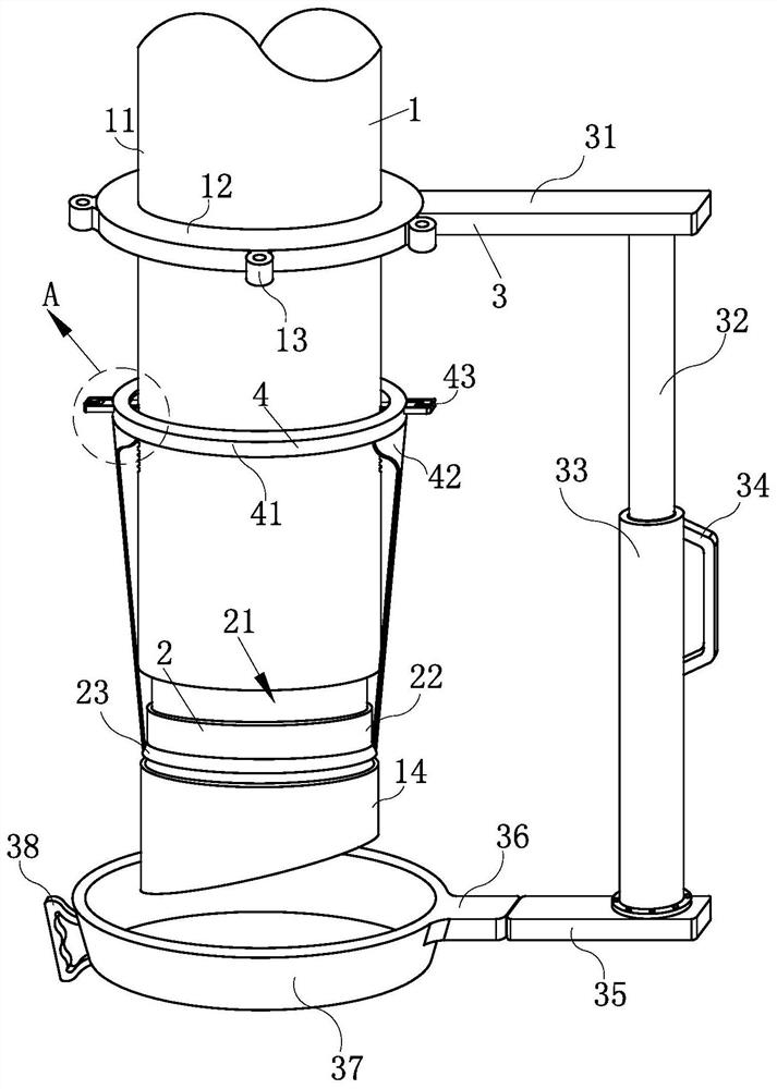
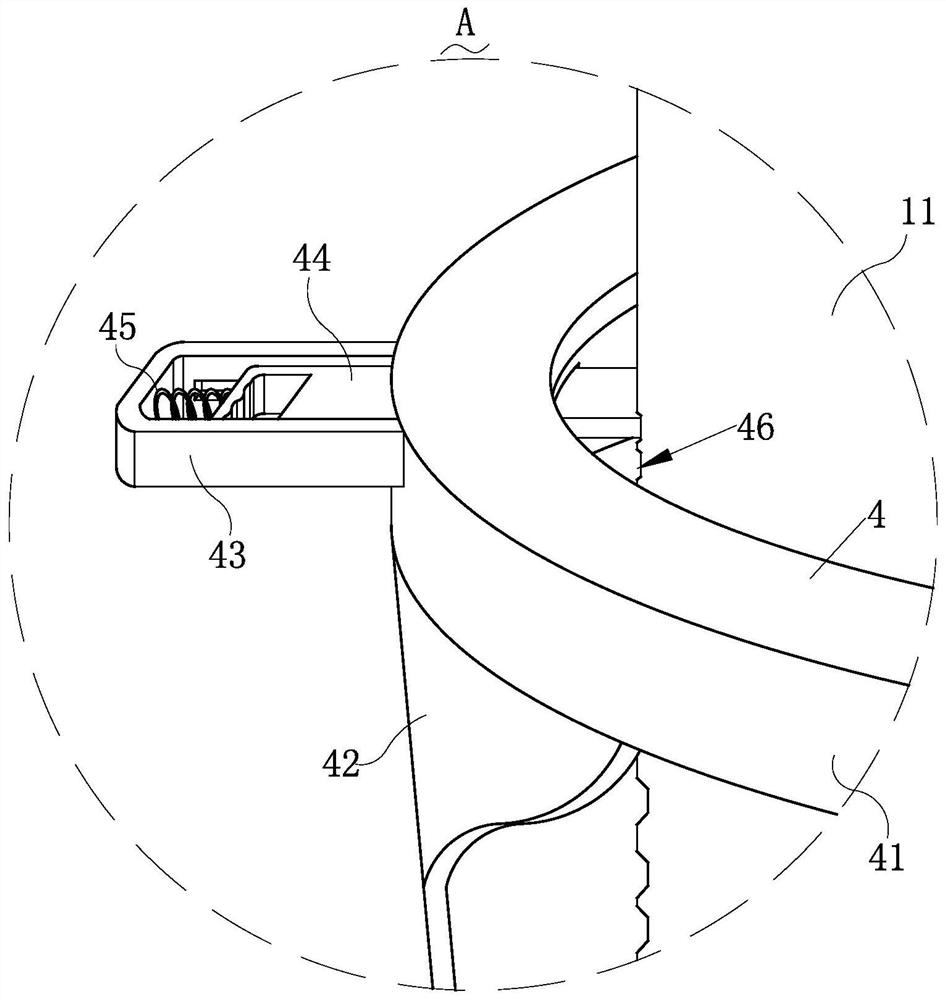
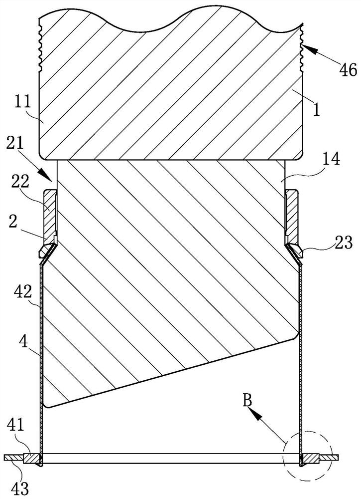
[0025]Such asFigure 1-Figure 7As shown, the protective device of a discharge pipe for powdered pesticide production according to the present invention includes a feeding mechanism 1, a fastening mechanism 2, a receiving mechanism 3, a protective mechanism 4, and a connecting mechanism 5, which are used to The side wall of the feeding mechanism 1 where pesticides are fed is installed with the receiving mechanism 3 for temporarily receiving pesticides, and the inside of the receiving mechanism 3 is installed with all means for realizing the overturning of the receiving mechanism 3. In the connecting mechanism 5, one end of the material receiving mechanism 3 is located at the bottom of the material discharging mechanism 1, and the side wall of the material dis...


PUM


Abstract

The invention relates to the technical field of powdery pesticide production, and particularly relates to a protection device of a discharging pipe for powdery pesticide production. The protection device comprises a discharging mechanism, a fastening mechanism, a receiving mechanism, a protection mechanism and a connecting mechanism, wherein the fastening mechanism is in threaded connection to theside wall of the discharging mechanism; the protection mechanism is arranged between the fastening mechanism and the discharging mechanism; during powdery pesticide discharging, the discharging mechanism and a receiving container are in cup joint through the protection mechanism, powdery pesticide protection is achieved, powdery pesticide scattering is avoided, and safety production is facilitated; the receiving mechanism is arranged on the side wall of the discharging mechanism, when the receiving container is replaced, the receiving mechanism can be rotated to the bottom of the dischargingmechanism, rapid temporary receiving is achieved, and powdery pesticide splashing is avoided; and the connecting mechanism is arranged in the receiving mechanism, when the receiving mechanism is filled with temporarily-received pesticide, one end of the receiving mechanism is pulled so that one end of the connecting mechanism can slide out of the receiving mechanism, the receiving mechanism is rotated to achieve overturning, and powdery pesticide cleaning is conducted.

Description

Technical field[0001]The invention relates to the technical field of powdered pesticide production, in particular to a protective device for a discharge tube for powdered pesticide production.Background technique[0002]Pesticides refer to chemical agents used in agriculture to control plant diseases and insect pests and regulate plant growth. It is widely used in agriculture, forestry and animal husbandry production, environmental and household hygiene, pest control and epidemic prevention, and mold and moth prevention of industrial products. There are many varieties of pesticides, which can be divided into insecticides, acaricides, rodenticides, nematicides, molluscicides, fungicides, herbicides, plant growth regulators, etc. according to their uses; they can be divided into minerals according to the source of raw materials Source pesticides (inorganic pesticides), biological pesticides (natural organics, microorganisms, antibiotics, etc.) and chemically synthesized pesticides; divi...

Claims


Application Information

Patent Timeline
IPC IPC(8): B65B1/28B65B1/06B65B39/06
CPCB65B1/28B65B1/06B65B39/06
Inventor 叶佳
Owner 安徽金泰农药化工有限公司
Learn More