Cavity casting and liner removing technique

A process and cavity technology, which is applied in the field of cavity casting and de-billing process, can solve the problems of increased cost, weight deviation, unqualified parts performance, etc., and achieves the effects of good cost, small weight deviation and cost control.

Inactive Publication Date: 2009-10-21
长沙水泵厂有限公司
View PDF0 Cites 0 Cited by
  • Summary
  • Abstract
  • Description
  • Claims
  • Application Information

AI Technical Summary

Problems solved by technology

[0003] Pattern production is divided into outer mold and core box. Due to the inconsistent hands of the operators, the control of the wall thickness of the model is uneven, and the thickness error reaches one-third, resulting in unqualified parts performance, weight deviation, and increased costs.

Method used


Image

  • Cavity casting and liner removing technique
  • Cavity casting and liner removing technique
  • Cavity casting and liner removing technique

Examples


Embodiment Construction

[0012] The present invention will be further described below in conjunction with the accompanying drawings and specific embodiments.

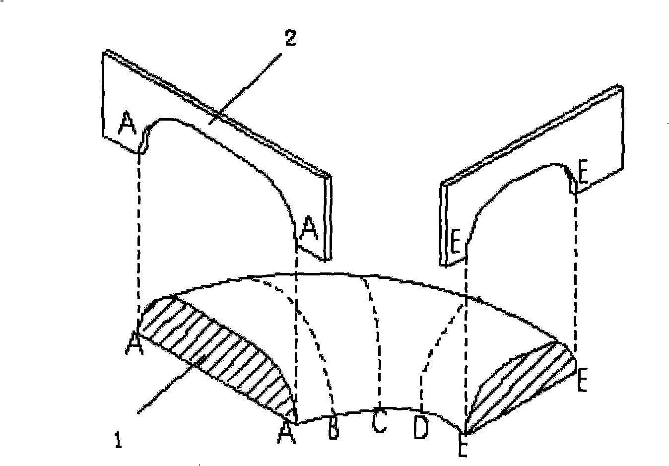
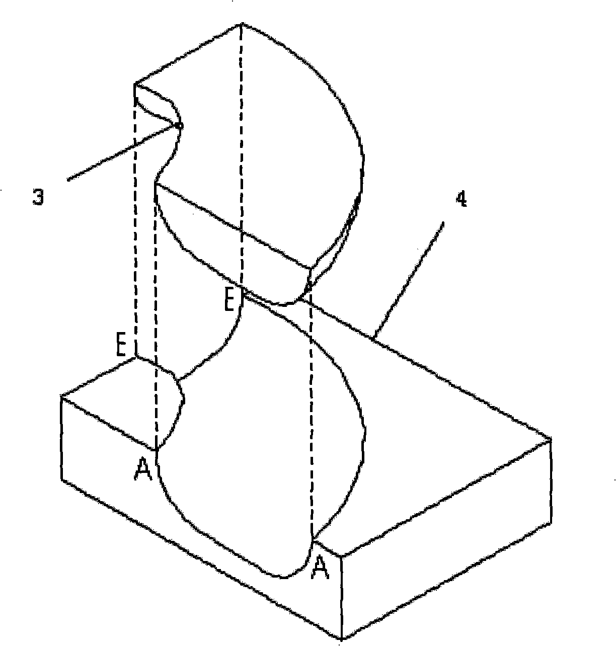
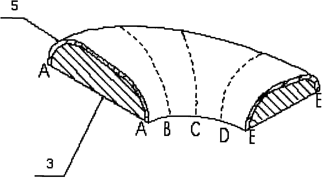
[0013] Bile removal is to make complex wooden molds with simple wooden molds. Figure 4 Parts shown, step 1, see figure 1 According to the shape of the inner cavity of the part 6 to be cast, a set of concave templates 2 for each section of A~E is made, positioned according to the size direction of the part drawing, and the shape of each section is shoveled on the dry wood with the template 2, and the sections are smoothly connected to form a wood Entity 1; Step 2, see figure 2 , use the wooden entity 1 to make a master mold in the plastic core box 4, and then make a plastic entity 3 on the master mold; the third step, see image 3 , on the plastic entity 3, nail the material with the same thickness as the part 6 to be cast, and connect it smoothly with plastic to form the outer mold pattern 5.

[0014] The mechanical parts produced by using...


PUM


Abstract

The invention discloses a cavity casting and liner removing technique which comprises the following steps: (1) first, a set of A-E templates with concave cross sections are manufactured according to the shapes of inner cavities of the parts which are needed to be casted and positioned according to the direction of drawing size of the parts, the shapes of all the cross sections are shoveled and scraped by the templates on the dry wood, and all the cross sections are smoothly connected with each other to form a wooden entity; (2) the wooden entity is used for making a female die in a plastic core box, then a plastic entity is made on a female die; (3) the material with the same thickness as the thickness of the parts needing to be casted is nailed up on the plastic entity and smoothly connected by plastics to form the appearance of an external die.

Description

technical field [0001] The invention relates to a casting process, in particular to a cavity casting gall removal process. Background technique [0002] In the design of mechanical parts, the internal and external shapes are connected smoothly through points, lines and surfaces, and become the cavity entity drawings of the parts. In production, many parts must be cast to meet the designer's requirements. Before casting, it is necessary to make a 1:1 shape that conforms to the geometric surface shape of the drawing according to the technical requirements of the drawing, so that the solid parts can be produced more accurately. [0003] Pattern making is divided into outer mold and core box. Due to the inconsistent hands of the operators, the wall thickness of the model is not uniformly controlled, and the plus or minus error of the thickness reaches one-third, resulting in unqualified parts performance, weight deviation, and increased cost. Contents of the invention [0004...

Claims


Application Information

Patent Timeline
Patent Type & Authority Applications(China)
IPC IPC(8): B22C7/00
Inventor 屈伟先蒋志云
Owner 长沙水泵厂有限公司
Why Eureka
Try Eureka