Car body structure

A technology of car body and car body length, which is applied in the direction of railway car body, railway car body parts, underframe, etc., which can solve the problems of rising cost of car body production, increased number of parts, and complicated structure under the floor, so as to avoid rigidity and strength Reduce, avoid the increase in the number of parts, and realize the effect of body production cost

Active Publication Date: 2009-10-21
HITACHI LTD
View PDF1 Cites 7 Cited by
  • Summary
  • Abstract
  • Description
  • Claims
  • Application Information

AI Technical Summary

Problems solved by technology

[0012] An object of the present invention is to provide a vehicle body structure in which various instruments and wiring or pipes connecting these instruments are arranged under the floor of the vehicle body, which does not cause a decrease in the rigidity of the bol...

Method used


Image

  • Car body structure
  • Car body structure
  • Car body structure

Examples


Embodiment Construction

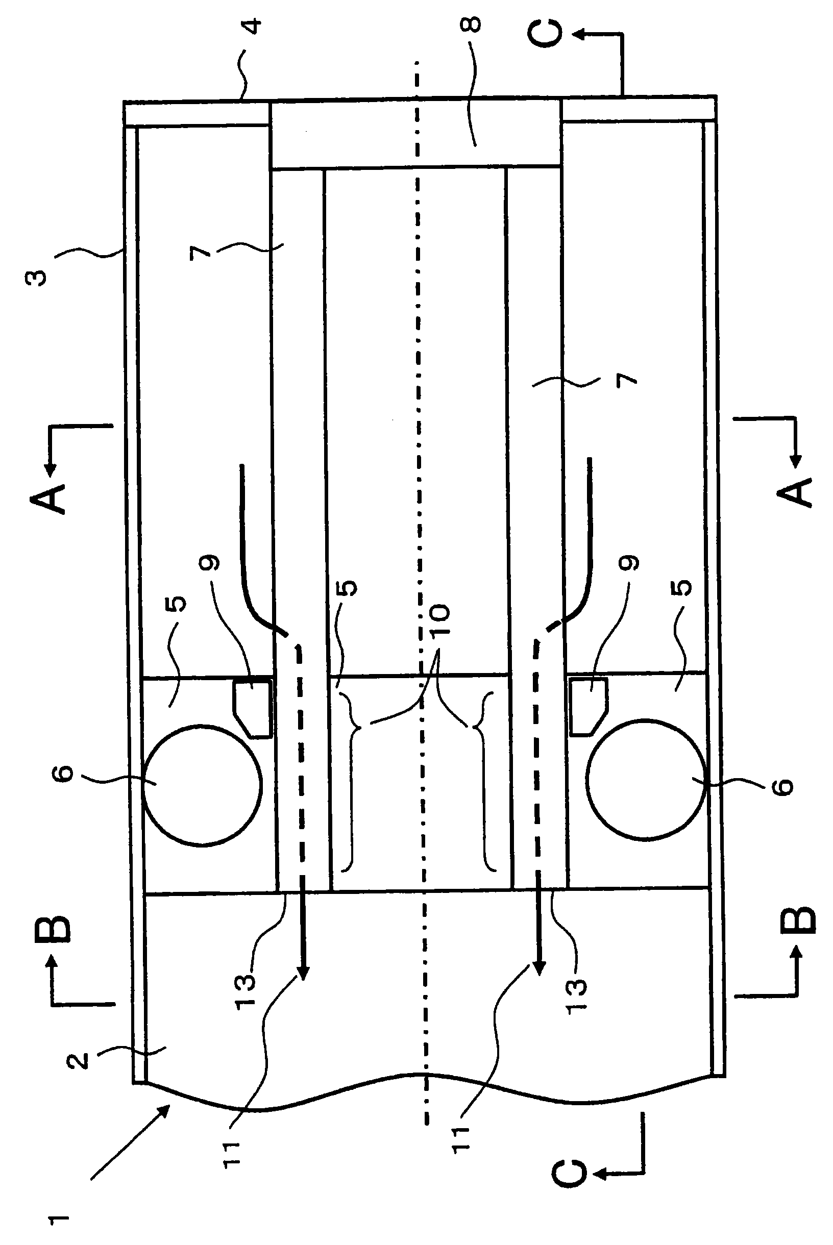
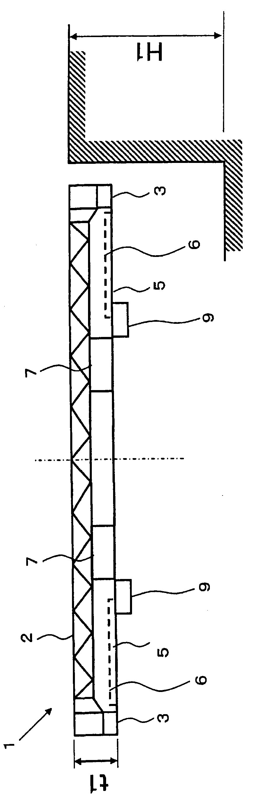
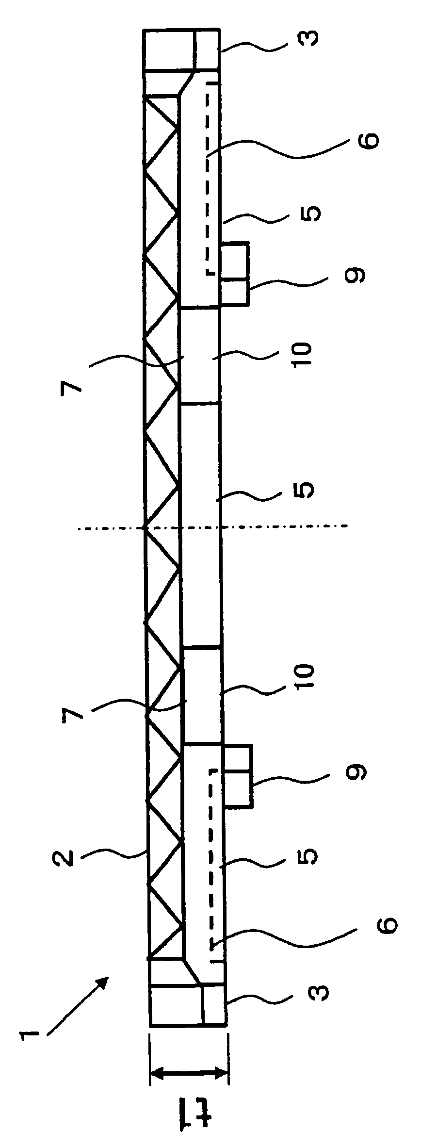
[0030] Hereinafter, embodiments of the vehicle body structure of the present invention will be described based on the drawings. figure 1 It is a bottom view showing one embodiment of the vehicle body structure of the present invention (the lower figure of the vehicle body viewed from the bottom frame side), figure 2 yes figure 1 A-A sectional view of the body structure shown, image 3 yes figure 1 B-B sectional view of the body structure shown, Figure 4 yes figure 1 C-C sectional view of the body structure shown. Figure 1 ~ Figure 4 Body structure shown with Figure 8 ~ Figure 9 The body structure shown is the same and is an embodiment with two center beams. figure 1 and Figure 4 The vehicle body structure is shown as a partial view including one end portion in the longitudinal direction.

[0031] exist Figure 1 ~ Figure 4 In the vehicle body structure shown, the bottom frame 1 is composed of: a floor panel 2 formed by arranging and joining a plurality of pa...


PUM


Abstract

The invention provides a car body structure capable of facilitating the laying operation of wires and pipes passing through a body bolster, preventing the increase of components and complexity of underfloor structure, and reducing the cost of manufacturing the car body without deteriorating the rigidity and strength of the body bolster. Center sills (7, 7) are passed through a body bolster (5) in an underframe (1), the intersection of center sills (7, 7) and the body bolster referred to as a penetration portion (10), wherein the inner space of the penetration portion (10) is used to arrange wires and pipes (the paths thereof shown by reference number (11)). The interior of the penetration portion is a rectangular hollow space capable of allowing a sufficient amount of wires and pipes to be passed therethrough. Since there is no need to provide to the body bolster conventional penetration pipes dedicated for arranging wires and pipes, and thus no voids are formed in the body bolster, the deterioration of rigidity and strength of the body bolster caused by such segmentalization of the body bolster can be prevented and the manufacturing cost can be cut down without increasing components such as reinforcement members.

Description

technical field [0001] The present invention relates to a body structure having a corbel under a floor and a center sill intersecting the corbel, and wiring or piping laid under the floor. Background technique [0002] In recent years, aluminum materials with excellent extrudability, corrosion resistance, and weldability have been developed for use in railway vehicles. Along with this, in railroad vehicles, from the viewpoint of weight reduction and production rationalization, a large-sized body made of aluminum alloy is now becoming mainstream. In particular, a vehicle body structure is proposed in which a hollow extruded aluminum profile (hereinafter referred to as a hollow extruded profile) made of an aluminum alloy that is advantageous in strength is required to bear a large compressive load on the vehicle end to form a floor. As such a vehicle body structure, the vehicle body structure described in Non-Patent Document 1 is mentioned, for example. [0003] The body is ...

Claims


Application Information

Patent Timeline
IPC IPC(8): B61F1/00
CPCB61D17/041Y02T30/34B61F1/12B61D17/04B61D17/10B61F5/04
Inventor 中村英之川崎健山本隆久
Owner HITACHI LTD
Why Eureka
Try Eureka