
Connecting plate on rear part of front grille of automobile and front part structure of automobile for mounting connecting plate

A front grille and connecting plate technology, applied to the upper structure, upper structure sub-assembly, vehicle parts, etc., can solve the problems of inconvenient access to tools and parts, and the lack of placement of maintenance tools and maintenance parts, etc., to achieve improved aesthetic effect

Active Publication Date: 2011-04-06
BEIQI FOTON MOTOR CO LTD
View PDF1 Cites 0 Cited by
  • Summary
  • Abstract
  • Description
  • Claims
  • Application Information

AI Technical Summary

Problems solved by technology

[0003] Passenger cars with the engine compartment arranged in front of the car and equipped with an engine compartment cover also have a structure in which the front grille and the engine cover are integrated, although the front grille and the engine cover are integrated to prevent human arms or hands from accidentally entering the vehicle. In the gap between the radiator and the front grille, it still does not have the function of placing maintenance tools and maintenance parts during car maintenance, which causes inconvenience in taking tools and parts during maintenance

Method used


Image

  • Connecting plate on rear part of front grille of automobile and front part structure of automobile for mounting connecting plate
  • Connecting plate on rear part of front grille of automobile and front part structure of automobile for mounting connecting plate
  • Connecting plate on rear part of front grille of automobile and front part structure of automobile for mounting connecting plate

Examples


Embodiment Construction

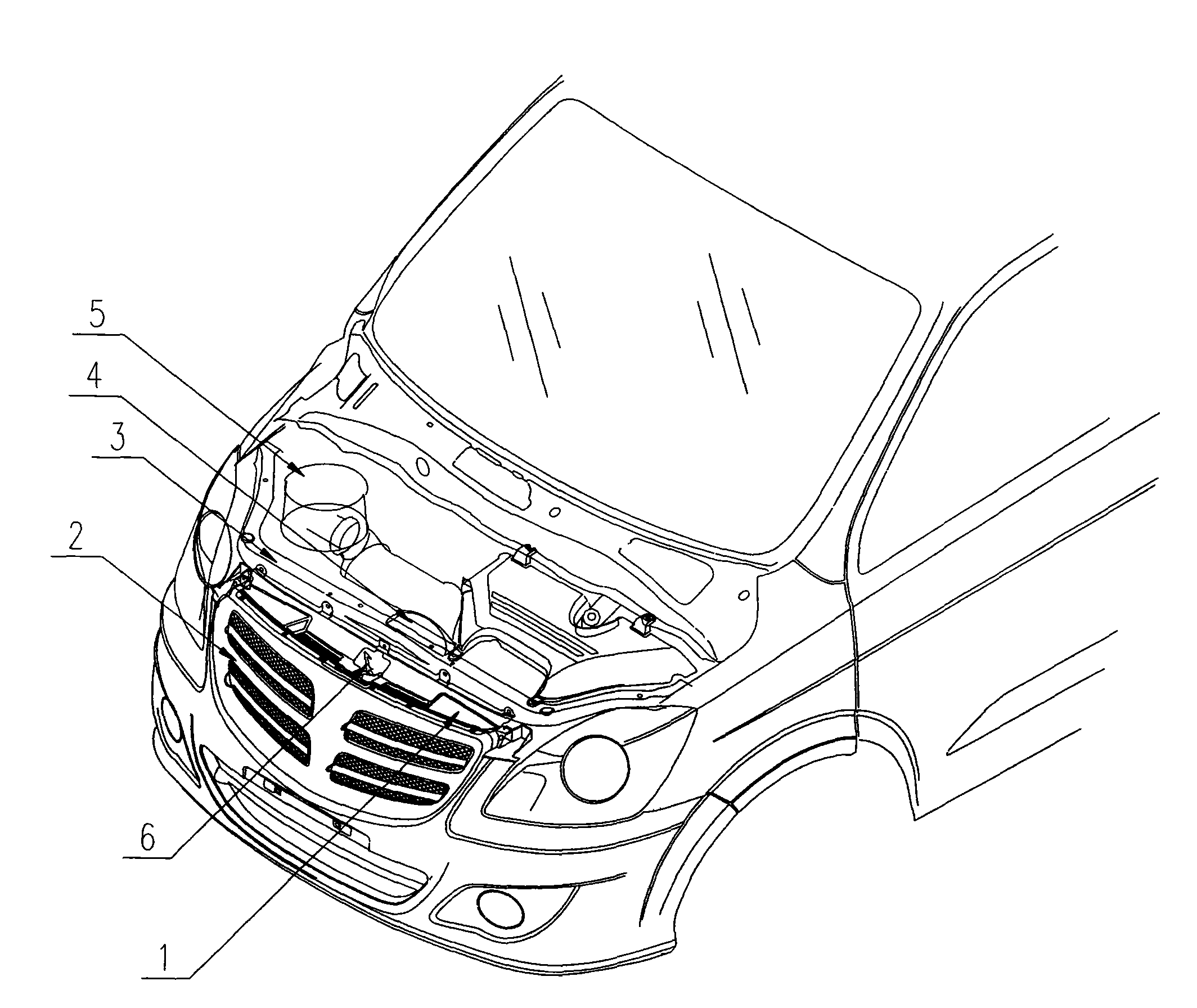
[0060] 6 Hood lock

[0061] The technical solution of the present invention will be described in detail below in conjunction with the accompanying drawings and specific embodiments to further understand the purpose, solution and effect of the present invention, but it is not intended to limit the scope of protection of the appended claims of the present invention.

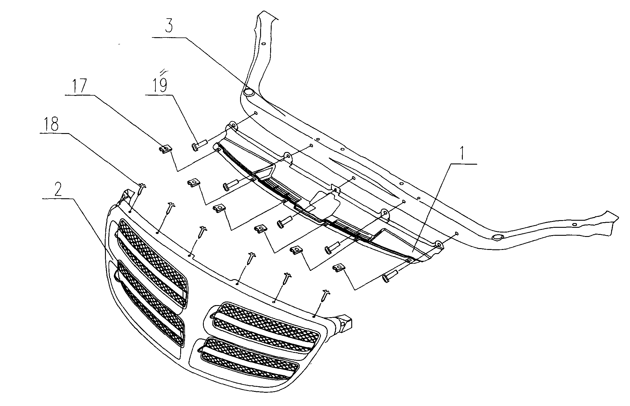
[0062] refer to figure 1 Schematic diagram of the structure of the front part of the automobile of the present invention and figure 2 The explosion diagram of the front structure of the car, the front structure of the car includes the front grille 2 of the car, the front beam 3 of the engine compartment and the connecting plate 1, wherein the connecting plate 1 is arranged between the front grille 2 of the car and the front beam 3 of the engine compartment, An air filter 5 is arranged in the engine compartment behind the front crossbeam 3 of the engine compartment, and the air filter 5 takes in air from the air ...


PUM


Abstract

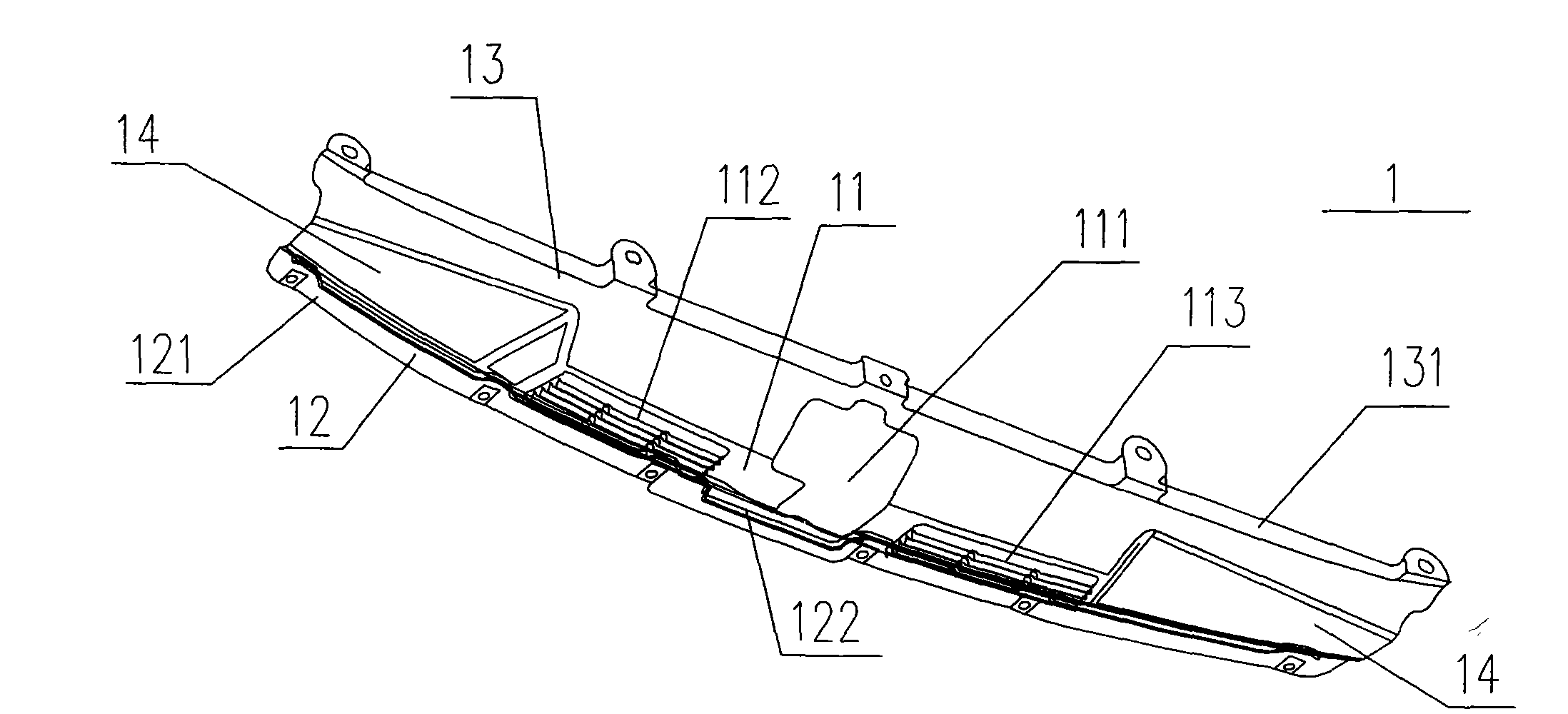
The invention relates to a connecting plate on the rear part of a front grille of an automobile and a front part structure of the automobile; the front part structure of the automobile comprises the front grille of the automobile, a front crossbeam of an engine room and the connecting plate; the connecting plate is arranged between the front grille of the automobile and the front crossbeam of theengine room and comprises a body extending along the direction of the automobile width, a front vertical plate extending upwards along the front part of the body and a rear vertical plate extending upwards along the rear part of the body and a platform, wherein the body is provided with an avoidance hole of an engine room hatch lock and a ventilated griller for ventilation and radiation; the middle upper part of the front vertical plate is provided with a front connecting side extending forwards; the front connecting side is connected with the front grille of the automobile; the rear verticalplate is provided with a connecting part connected with the front crossbeam of the engine room; and the platform is arranged at two sides of the body, is enclosed with the front vertical plate and therear vertical plate and is used for placing maintenance tools. The connecting plate can prevent the arms and hands of people from entering a gap between the front grille and a radiator by mistake, can promote the attractive appearance of the engine room of the automobile and has the function of placing the maintenance tools and maintenance parts.

Description

technical field [0001] The invention relates to a front structure of a passenger car, in particular to a connecting plate at the rear of the front grille of a passenger car. Background technique [0002] At present, passenger cars with engine compartments arranged in front of the car and equipped with engine compartment covers mostly adopt the structure disclosed in the Chinese invention patent application with the application number "200810149288.3" and the name "automobile front structure", that is, the radiator Supported on the body parts by the support part of the fixed frame, the front part of the radiator is provided with a front grille, and the upper part of the radiator is connected with the engine cover through the fixed frame (see Fig. 14 and Fig. 15 in the patent publication). It can be seen from the figure It is pointed out that the vehicle front structure of this structure does not have the function of arranging maintenance tools and maintenance parts during veh...

Claims


Application Information

Patent Timeline
Patent Type & Authority Patents(China)
IPC IPC(8): B62D25/08B60R19/26B60R19/52B60R11/06
Inventor 陶冶李维增张志亮
Owner BEIQI FOTON MOTOR CO LTD
Learn More