Check patentability & draft patents in minutes with Patsnap Eureka AI!

Backlight module structure

A technology of backlight module and light guide plate, applied in optics, nonlinear optics, instruments, etc., can solve the problems of difficult positioning, broken holes, inconvenient assembly, etc.

Inactive Publication Date: 2009-10-21
WINTEK CORP
View PDF0 Cites 5 Cited by
  • Summary
  • Abstract
  • Description
  • Claims
  • Application Information

AI Technical Summary

Problems solved by technology

[0008] In view of the lack of conventional technology, the purpose of the present invention is to propose a backlight module structure, which not only enables the light guide plate to be firmly fixed on the frame, but also increases the attachment area between the display module and the frame, effectively improves the drop test, and enhances the structural strength. It can solve the problems of inconvenient assembly, difficult positioning and broken holes that may occur after the traditional display module is thin.

Method used


Image

  • Backlight module structure
  • Backlight module structure
  • Backlight module structure

Examples


Embodiment Construction

[0061] The technical means and effects used by the present invention to achieve the purpose will be described below with reference to the attached drawings, and the embodiments listed in the following drawings are only for auxiliary explanation, to facilitate understanding, but the technical means of the present invention are not limited The diagrams listed.

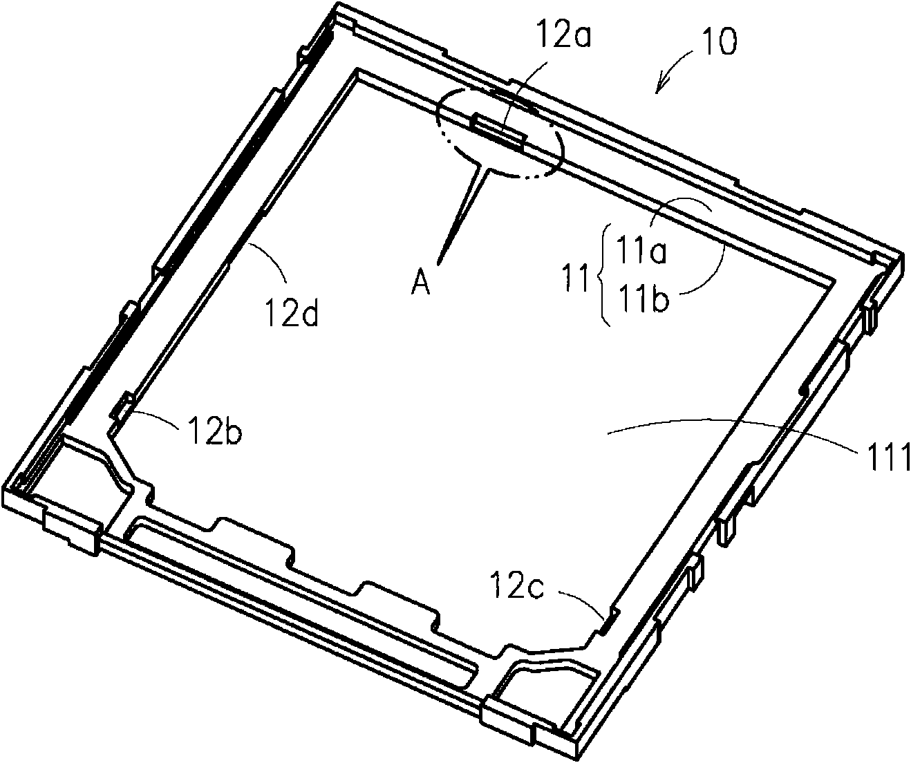
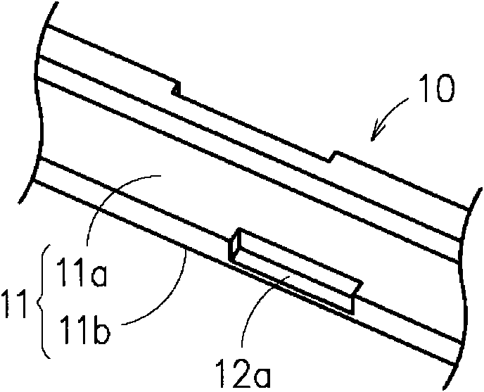
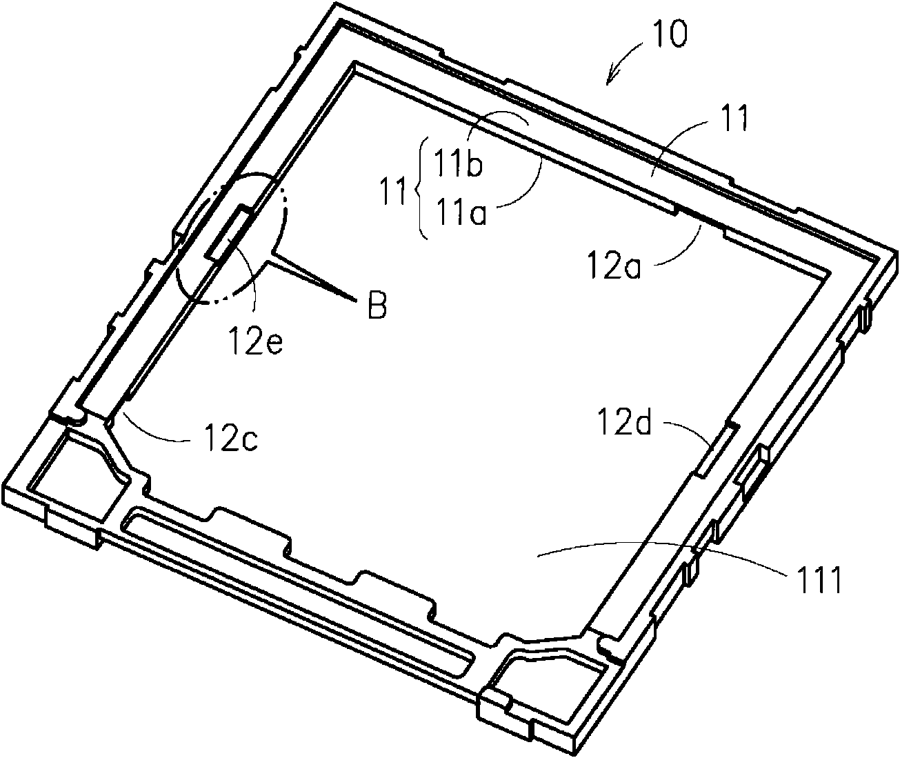
[0062] See first Figure 9 to Figure 12 As shown, the backlight module structure proposed by the present invention includes a frame 30, the frame 30 has a bearing portion 31, the bearing portion 31 has a front 31a and a back 31b, wherein the front 31a is used to directly carry a liquid crystal display Module (not shown in the figure), the bearing part 31 has a generally rectangular accommodation hole 311, and the periphery of the accommodation hole 311 is provided with a plurality of flanges 32a-32d, and a plurality of grooves 32e, 32f, and the flange 32a-32d and the grooves 32e, 32f are misaligned with each other; in t...


PUM


Abstract

The invention provides a backlight module structure which comprises a frame and a light guide plate. The frame is provided with a bearing part, one surface of the bearing part is used for bearing a display module, the bearing part is provided with a plurality of flanges and a plurality of grooves, and the flanges are misplaced with the grooves. The light guide plate is held in the frame and is correspondingly provided with a positioning groove and a positioning sheet, and the positioning groove and the positioning sheet of the light guide plate is clamped with the flanges and the grooves of the frame, thereby stably positioning the light guide plate in the frame, increasing attachment area of the display module and the frame, effectively improving structure intensity, and solving the problem of inconvenient assembly, difficult positioning, broken holes, and the like, possibly caused by thin form of the prior backlight module.

Description

technical field [0001] The invention relates to a backlight module structure, in particular to a backlight module structure which can not only fix the light guide plate stably on the frame, but also increase the attachment area between the display module and the frame, effectively improve the drop test, and enhance the structural strength. Background technique [0002] The thinner backlight module is the trend of the times, in order to achieve the thinner module, generally adopt the structure, such as Figure 1 to Figure 4 The structure of a known frame (Housing) 10 is shown, and as Figure 5 and Figure 6 The light guide plate 20 matched with the frame 10 is shown; the frame 10 has a bearing portion 11, and the bearing portion 11 includes a front side 11a and a back side 11b, wherein the front side 11a is used to carry a liquid crystal display module (not shown in the figure) Out), the bearing part 11 has a generally rectangular accommodation hole 111, the periphery of the...

Claims


Application Information

Patent Timeline
IPC IPC(8): G02F1/13357G02F1/1333G02F1/1335
Inventor 林明传王星发王士诚
Owner WINTEK CORP
Features
  • R&D
  • Intellectual Property
  • Life Sciences
  • Materials
  • Tech Scout
  • Unparalleled Data Quality
  • Higher Quality Content
  • 60% Fewer Hallucinations
Learn More