

Electric connector
An electric connector and a common technology, applied in the direction of conductive connection, connection, clamping/spring connection, etc., can solve the problems of poor electrical conductivity of the terminal, small current-carrying area of the solder piece, and increase the difficulty of processing, etc., to achieve withstand voltage The effect of higher values, better overall performance, and increased creepage distance
- Summary
- Abstract
- Description
- Claims
- Application Information
AI Technical Summary
Problems solved by technology
Method used
Image

Examples
Embodiment 1
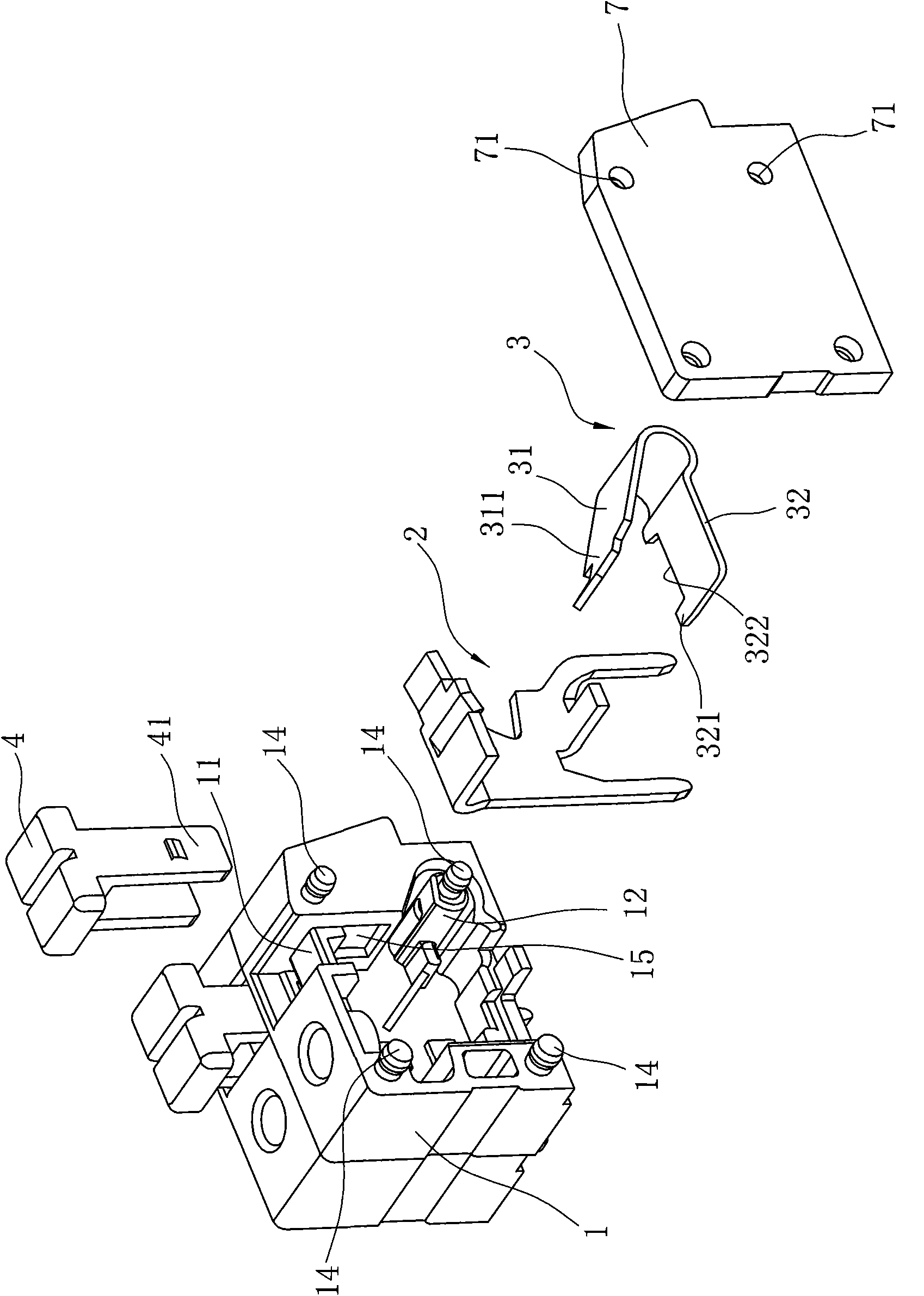
[0026] Embodiment one, refer to Figure 1 ~ Figure 4 Shown:
[0027] The electrical connector of the first embodiment includes two insulating bases 1 that are spliced together, and each base 1 is provided with a wiring hole 15 for insertion of wires in the front;
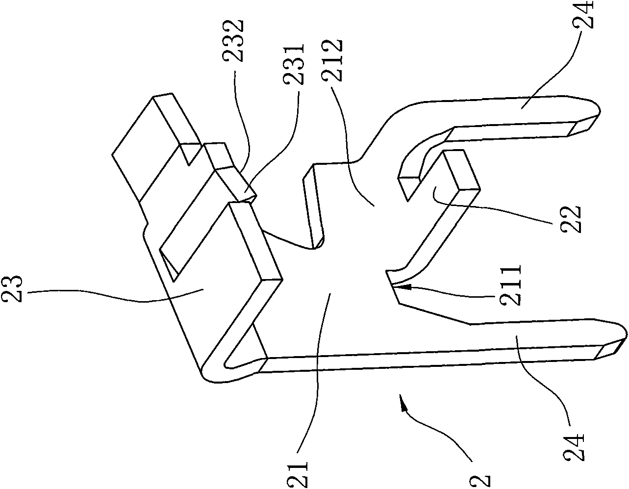
[0028] The soldering piece 2 fixedly arranged in the base 1, the soldering piece 2 acts as a carrier fluid, and is used to realize the electrical connection between the wire and the circuit board;
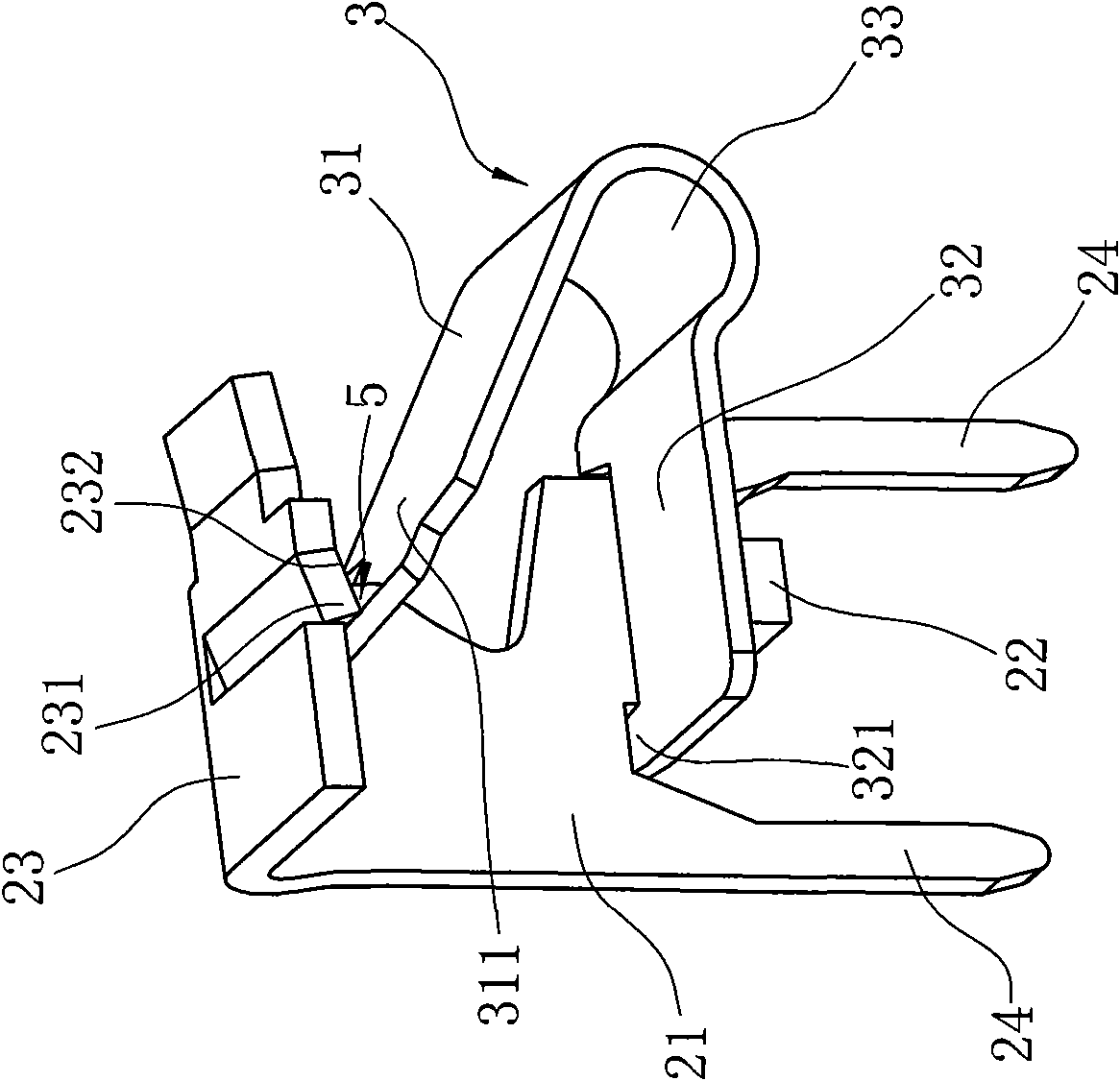
[0029] The elastic piece 3 connected to the welding piece 2, the elastic piece 3 includes a free end 311 which has a tendency to always abut against the welding piece 2 and a fixed end 321 connected to the welding piece 2;
[0030] The button 4 installed on the top of the base, the cross section of the button is in the shape of "Ji", the base 1 is provided with a beam 11 that can be inserted into the Z-shaped button, the bottom end 41 of the button 4 and the free end of the shrapnel 3 311 offset, pressing down on the...
Embodiment 2
[0037] Embodiment two, refer to Figure 5 ~ Figure 8 Shown:
[0038] The basic structure of the second embodiment is the same as that of the first embodiment. The difference between the two is that the base 1 also has a through hole 13 on the outer wall near the bottom, which can be inserted into the conductive bridging piece 6, wherein the conductive The bridge piece 6 is generally an electric conductor with two pins 61, which can realize rapid conduction of the circuit between adjacent bases. The current-carrying main board 21 of the solder piece 2 is also formed with a current-carrying pin at the position corresponding to the through hole 13. The main board 21 is perpendicular to the side plate 25 , and the side plate 25 defines a hole 251 through which the pin 61 of the conducting bridge 6 can pass and is aligned with the through hole 13 .
[0039] If it is necessary to realize the rapid conduction of the circuit between the two bases, as long as the two pins 61 of the co...
PUM
 Abstract
Description
Claims
Application Information