Miniature motor

A motor, small technology, applied in the direction of DC commutator, mechanical energy control, electric components, etc., can solve the problems of effective magnetic flux reduction, not easy to bend, and winding space to ensure obstacles, so as to ensure effective magnetic flux and prevent Winding hook hooked to the bending part, mechanical noise and vibration reduction effect

Inactive Publication Date: 2009-10-21
MABUCHI MOTOR
View PDF0 Cites 5 Cited by
  • Summary
  • Abstract
  • Description
  • Claims
  • Application Information

AI Technical Summary

Problems solved by technology

As mentioned above, when a multi-pole core structure is used to reduce jerk, the provision of a wide portion hinders the securing of a winding space.
In addition, the bending process of the connecting portion of the illustrated core-shaped wide portion is unstable.
Patent Document 3 does not clearly disclose the shape of the bent portion viewed from the side, but processing is difficult unless a gap is provided between the stacked cores adjacent to the axial direction.
In short, if you do not set Figure 7 blade portion as shown or Figure 8 cutouts as shown, cannot be easily bent
Effective flux decreases if gap is set

Method used


Image

  • Miniature motor
  • Miniature motor
  • Miniature motor

Examples


Embodiment Construction

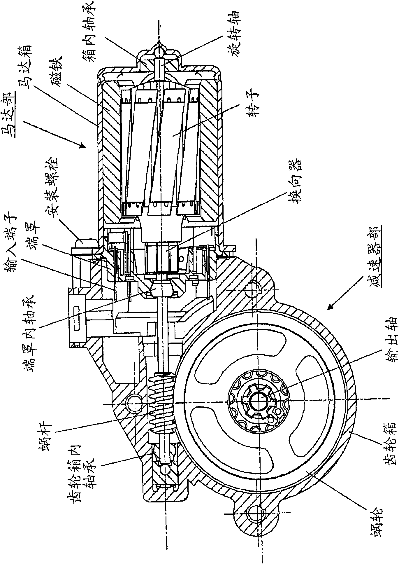
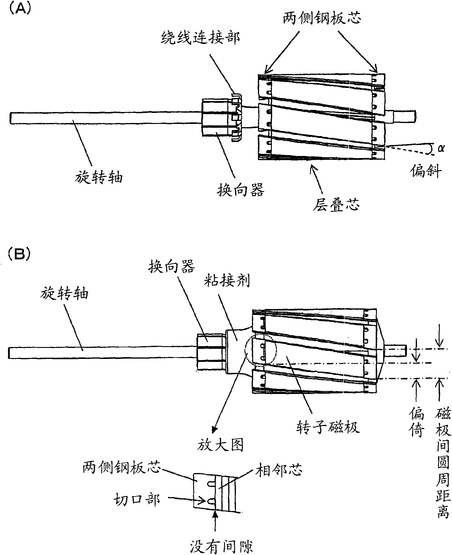
[0027] Hereinafter, the present invention will be described based on examples. figure 1 It is a longitudinal sectional view of a motor with a speed reducer constructed based on the present invention. This motor with a speed reducer has a structure in which a motor part and a speed reducer part are integrally assembled. The motor unit has a magnet attached to the inner peripheral surface of a bottomed hollow cylindrical motor case made of a metal material. The opening of the box is fitted with a resin end cover (Endbell) to close it. The rotating shaft is equipped with rotating magnetic poles and commutators composed of laminated cores wound with windings to form a rotor (see figure 2 ). In addition, a pair of input terminals connected to a pair of brushes contacting the commutator protrude outside the motor through the end cover for electrical connection. One end of the rotating shaft is supported by an in-box bearing provided at the bottom center of the bottomed hollow ...


PUM


Abstract

A rotor pole laminated core assembly is formed by means of stacking a predetermined number of steel plate cores and two end steel plate cores such that one of the end steel plate cores is located at one end of the laminated core assembly and the other end steel plate core is located at the other end of the laminated core assembly. Each of the end steel plate cores includes bent portions extending from ends of radially extending arm portions. The bent portions are wider than the arm portions and circumferentially extend toward adjacent poles. Each wide bent portion, which extends from the corresponding arm portion, has cutouts located on opposite sides of the arm portion.

Description

technical field [0001] The present invention relates to a small motor provided with a steel plate core on both sides, each of which is formed by bending radial end portions outwardly of an axis on both sides of a laminated core of a rotor magnetic pole. Background technique [0002] In small motors, it is known to reduce the thickness of the motor by reducing the axial length of the core for rotor magnetic poles, and to secure the magnetic flux without degrading the performance of the motor. A technique in which the ends are bent toward the outside of the shaft to concentrate the magnetic flux. [0003] Figure 7 Indicates a conventional rotor pole core with its ends bent, Figure 7 (A) and Figure 7 (B) represents one sheet each on both sides of the laminated core (see Patent Document 1). The illustrated core consists of an annular portion having a central hole fitted into the motor shaft, arms extending radially therefrom as many as the number of rotor magnetic poles, and...

Claims


Application Information

Patent Timeline
Patent Type & Authority Applications(China)
IPC IPC(8): H02K1/26H02K7/116H02K23/04
CPCH02K2201/06H02K7/1166H02K1/24H02K1/26H02K23/40
Inventor 佐谷务
Owner MABUCHI MOTOR
Why Eureka
Try Eureka