Supercharge Your Innovation With Domain-Expert AI Agents!

Light-emitting diode lamp

一种发光二极管、灯具的技术,应用在发光元件的半导体器件、光源、电光源等方向,能够解决灯具照射面积有限、照射方向单一等问题,达到良好照明效果的效果

Inactive Publication Date: 2009-10-28
FU ZHUN PRECISION IND SHENZHEN +1
View PDF0 Cites 3 Cited by
  • Summary
  • Abstract
  • Description
  • Claims
  • Application Information

AI Technical Summary

Problems solved by technology

Due to the single irradiation direction of the plane light source, the irradiation area of ​​the lamp is limited

Method used


Image

  • Light-emitting diode lamp
  • Light-emitting diode lamp
  • Light-emitting diode lamp

Examples


Embodiment Construction

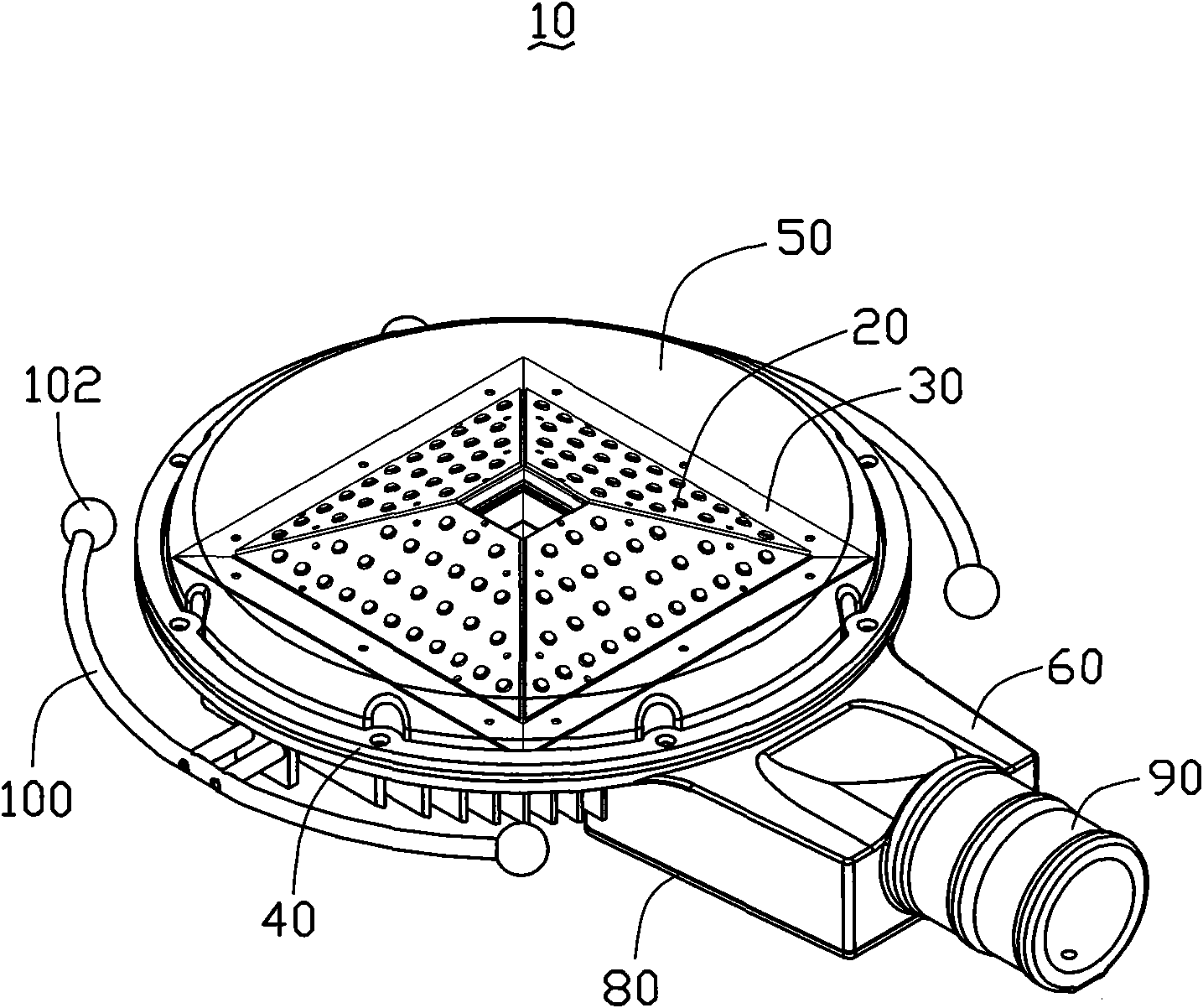
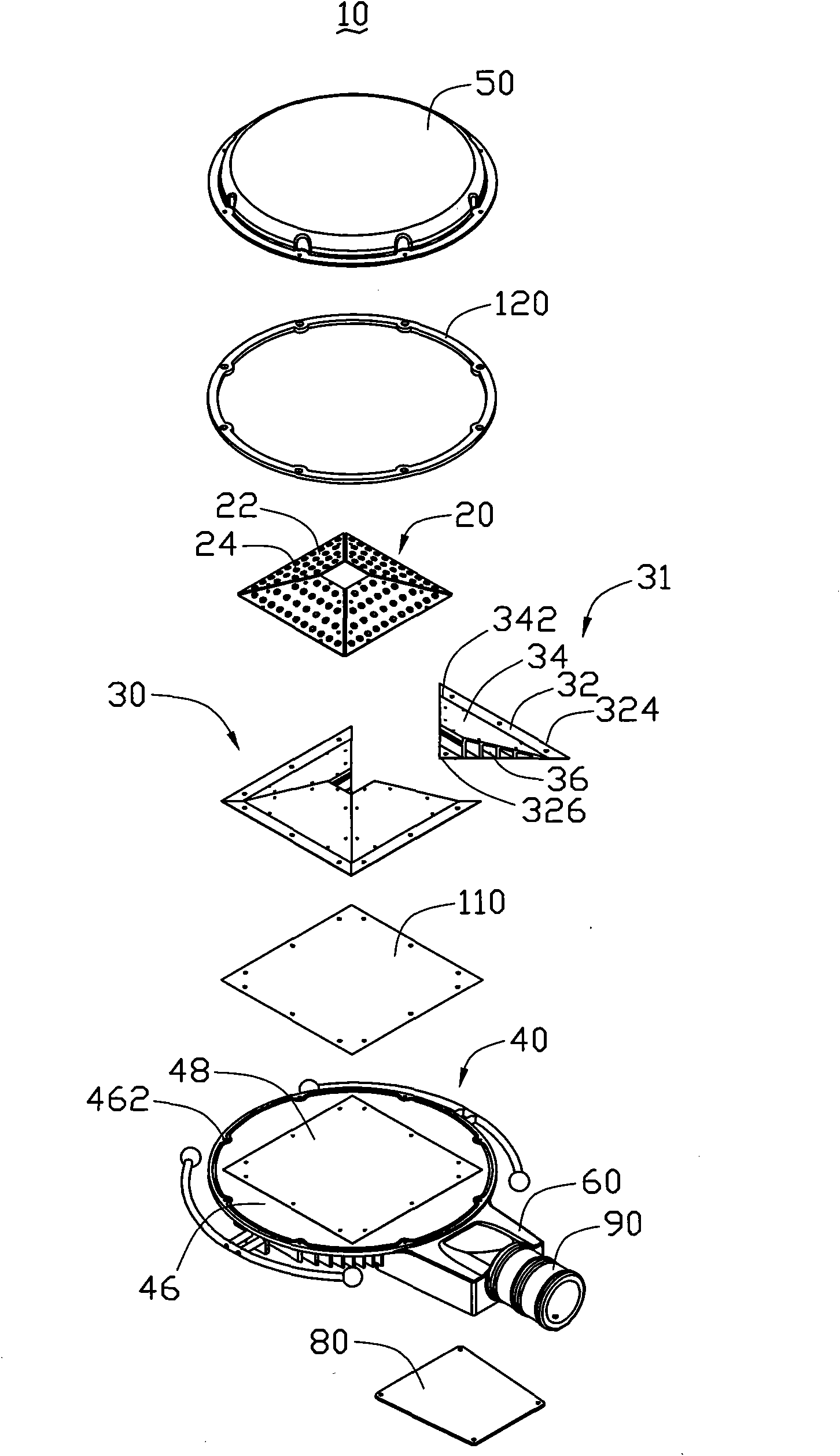
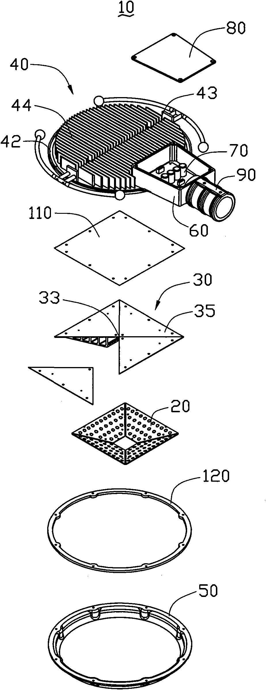
[0011] see figure 1 and image 3 The light emitting diode lamp 10 of the present invention includes several light emitting diode modules 20, a heat absorber 30 for attaching the light emitting diode module 20, a heat sink 40 located at one end of the heat absorber 30 and connected to it, and a heat sink 40 arranged on the heat sink 40 on one side and cooperate with the radiator 40 to cover the light-emitting diode module 20 and the heat absorber 30 inside a lampshade 50, a housing 60 protruding from the side end of the radiator 40 and cooperate with the housing 60 There is a cover 80 for accommodating a driving circuit module 70 therein. A cylindrical joint 90 is mounted on the end of the housing 60 away from the radiator 40 for connecting with a light pole (not shown). The driving circuit module 70 is used to electrically connect with the LED module 20 .

[0012] see figure 2 Each LED module 20 includes a trapezoidal circuit board 22 and a plurality of LEDs 24 uniformly ...


PUM


Abstract

The invention relates to a light-emitting diode lamp which comprises a plurality of light-emitting diode modules and a lamp shade covering the light-emitting diode modules therein, and also comprises a heat receiver and a radiator, wherein the heat receiver is positioned in the lamp shade and used for being attached by the light-emitting diode modules, and the radiator is arranged outside the lampshade and connected with the heat receiver, the heat receiver is provided with a plurality of top plates with different directions and a plurality of bottom plates opposite to the top plates, a plurality of airflow channels are formed between the top plates and the bottom plates, the light-emitting diode modules are attached on the top plates, and the top of the heat receiver forms a space. Compared with the prior art, because the top plates of the heat receiver face to different direction, the light-emitting diode modules positioned on the top plates face to different direction, the region irradiated by the light-emitting diode lamp is wider than that irritated by the traditional light-emitting diode lamp, and better illuminating effect is achieved by the light-emitting diode lamp.

Description

technical field [0001] The invention relates to a lighting device, in particular to a light emitting diode lamp. Background technique [0002] As an emerging third-generation light source, light-emitting diode light source has many characteristics such as long working life, environmental protection, power saving, and long life. Moreover, the current modules composed of light-emitting diodes can produce high-power, high-brightness light sources, so they will widely and revolutionaryly replace existing light sources such as traditional incandescent lamps, and then become the main light source in line with the theme of energy conservation and environmental protection. [0003] However, as the power and brightness of LEDs or their modules increase, the heat generated by them will also increase. If the heating problem of LEDs cannot be solved in time, the working life of LED lamps will be seriously affected. Therefore, the industry generally installs a heat sink on the LED modul...

Claims


Application Information

Patent Timeline
Patent Type & Authority Applications(China)
IPC IPC(8): F21V29/00F21V19/00H01L23/367F21Y101/02
CPCY10S362/80F21V29/246F21V29/004F21V29/2262F21V19/001F21Y2111/007F21S6/00F21V29/2243F21Y2101/02F21V29/75F21V29/76F21V29/89F21Y2115/10F21Y2107/40F21V29/71F21V29/763
Inventor 郑世崧
Owner FU ZHUN PRECISION IND SHENZHEN
Features
  • R&D
  • Intellectual Property
  • Life Sciences
  • Materials
  • Tech Scout
  • Unparalleled Data Quality
  • Higher Quality Content
  • 60% Fewer Hallucinations
Learn More