
MOS component testing method

A technology of MOS devices and testing methods, which is applied in the direction of single semiconductor device testing, semiconductor/solid-state device testing/measurement, components of electrical measuring instruments, etc., and can solve the problem of large fluctuations in test conduction resistance and unstable test signals, etc. problem, to achieve the effect of reducing test signal interference, improving stability and accuracy, and improving stability and reliability

Inactive Publication Date: 2009-10-28
SEMICON MFG INT (SHANGHAI) CORP
View PDF0 Cites 10 Cited by
  • Summary
  • Abstract
  • Description
  • Claims
  • Application Information

AI Technical Summary

Problems solved by technology

[0003] The purpose of the present invention is to provide a method for testing MOS devices, so as to solve the problem that the test signal drawn from the source end test pin of the MOS device tested by the traditional MOS device test method using the probe card is unstable, resulting in large fluctuations in the on-resistance value of the test. The problem

Method used


Image

  • MOS component testing method
  • MOS component testing method

Examples


Embodiment Construction

[0009] The method for testing a MOS device of the present invention is applied to testing the on-resistance of a wafer-level MOS device by using a probe card. According to the test requirements of different MOS devices, the probe card can choose probe cards with different pin numbers for testing. Several probes on the probe card are in contact with the source end of the MOS device, and a single needle is in contact with the gate of the MOS device as a gate loading probe. Each probe is connected with lead wires to lead out several connection points. The wiring points are distributed on the probe card, and are binding posts or wiring soldering points on the probe card. Use several probes on the probe card as source test probes, connect several connection points as source test probes for electrical continuity, and use several probes on the probe card as source load probes Needle, connect several connection points as source loading probes for electrical continuity. Since the co...


PUM


Abstract

The invention provides an MOS component testing method used for testing on-resistance of an MOS component with a probe card. The probe card is provided with a plurality of probes for being contacted with a source end of the MOS component. The probes lead out a plurality of wiring points in a connected way, which are respectively positioned on the probe card, by leading wires. A plurality of probes of the probe card are used as source end testing probes. The wiring points of the probes as the source end testing probes undergo electric conduction connection. A plurality of probes of the probe card are used as source end loading probes. The wiring points of the probes as the source end loading probes undergo electric conduction connection so as to joint the leading wires of the probes. The accuracy and the interference resistance capability of source end test signals can be effectively improved, the stability of an on-resistance test value can be improved, and the problem that in a conventional testing method, the on-resistance test value largely fluctuates as the test signals are easily interfered is solved.

Description

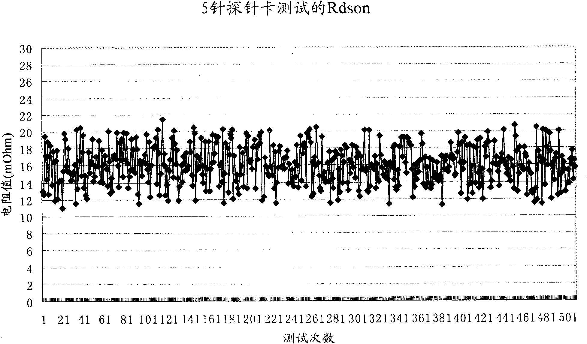
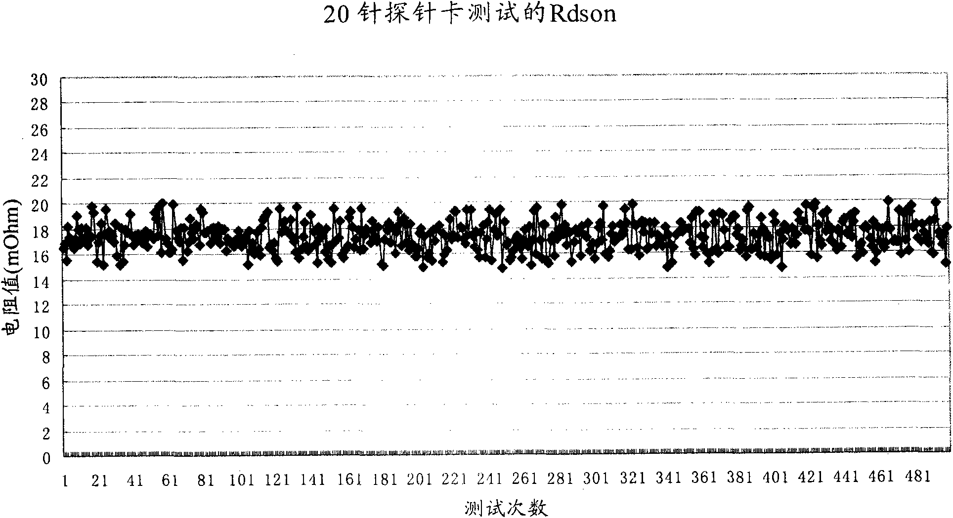
technical field [0001] The invention relates to the field of testing MOS devices, in particular to a testing method for a MOS device applied to a probe card for testing the on-resistance of a wafer-level MOS device. Background technique [0002] CP (Circuit Probe) testing will be performed on wafer-level MOS devices before packaging the wafers on which the MOS devices are fabricated. During the CP test, the on-resistance (R dson ) is a very critical parameter. R dson It directly determines the power consumed when the MOS device is turned on. Therefore, it is particularly important to test this parameter for low-power integrated chips. The on-resistance of wafer-level MOS devices is usually tested with a probe card. The probe card (Probe Card) is usually divided into probe cards with 5 probes, probe cards with 20 probes and other probe cards with different numbers of probes. needle card. The probes are connected by lead wires to lead out several connection points respe...

Claims


Application Information

Patent Timeline
Patent Type & Authority Applications(China)
IPC IPC(8): G01R31/26G01R1/073G01R27/02H01L21/66
Inventor 刘铁鲜益民柳入华郭万瑾
Owner SEMICON MFG INT (SHANGHAI) CORP
Learn More