
Method for realizing synchronous work of infrared scanning and camera and system thereof

A technology of infrared scanning and synchronous work, applied in the input/output process of data processing, instruments, electrical digital data processing, etc., can solve the problems of long scanning time and shooting time, inaccurate judgment of touch points, affecting touch positioning accuracy, etc. , to improve the accuracy, shorten the infrared scanning time, and improve the analysis and processing speed.

Inactive Publication Date: 2011-04-20
GUANGDONG VTRON TECH CO LTD
View PDF0 Cites 0 Cited by
  • Summary
  • Abstract
  • Description
  • Claims
  • Application Information

AI Technical Summary

Problems solved by technology

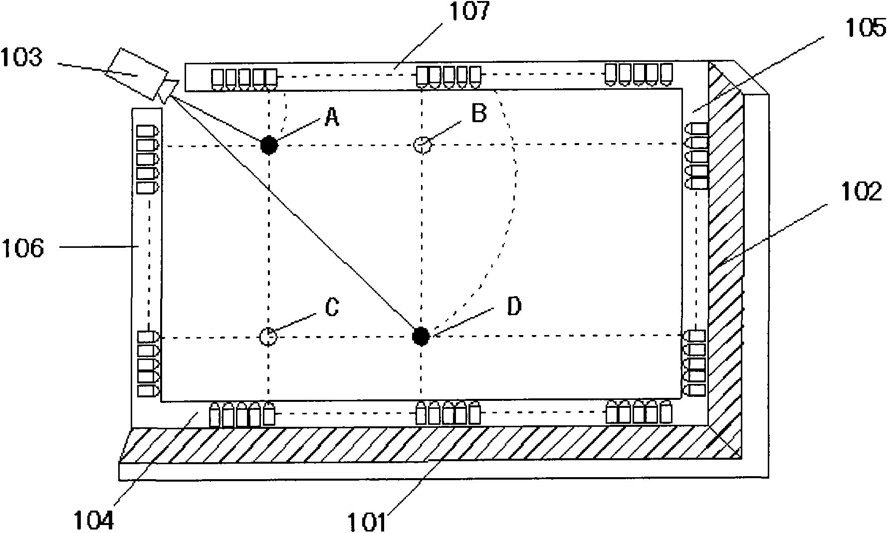
[0003] This method of combining infrared scanning and camera for touch positioning requires strict synchronization between infrared scanning and camera shooting. If synchronization cannot be ensured, for example, the camera captures the 1 The touch point is at position A at all times, and the infrared scanning needs to scan the entire infrared frame, and the scanning time is generally longer than the camera shooting time, resulting in t 2 The position of the touch point is detected at a moment, but the position of the touch point may have moved at this time, and the touch point detected by the infrared scan is at position B. When the final coordinates are determined by comprehensive infrared scan and camera analysis, it will appear Error, which affects the positioning accuracy of the touch
At present, the existing infrared scanning and camera combination system generally has this problem, which makes the judgment of the position of the touch point not accurate enough, and the judgment time is also greatly extended.

Method used


Image

  • Method for realizing synchronous work of infrared scanning and camera and system thereof
  • Method for realizing synchronous work of infrared scanning and camera and system thereof
  • Method for realizing synchronous work of infrared scanning and camera and system thereof

Examples


Embodiment

[0032] This embodiment is a method for achieving synchronization of infrared scanning and camera work, such as Figure 4 As shown, including the following steps:

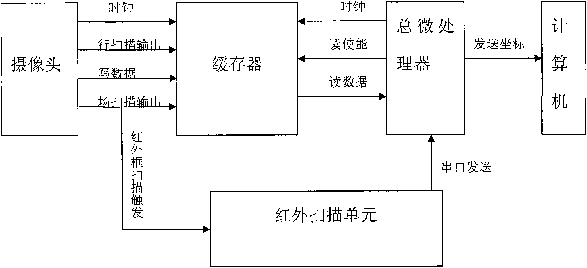
[0033] (1) Start the camera, and use the field scan output signal of the camera as the trigger signal of the infrared scanning unit to start the infrared transmitting module and infrared receiving module in the infrared scanning unit; Figure 5 As shown in the sequence diagram, the process is specifically:

[0034] When the camera starts, it outputs the field scanning signal, the camera starts to scan the field, and at the same time triggers the infrared transmitting module and infrared receiving module in the infrared scanning unit to start scanning, and the microprocessor in the infrared receiving module starts to collect the ADC of each infrared receiving tube Value, where each diode of the infrared transmitting module works synchronously with each diode of the corresponding infrared receiving module.

[0035] (2) After...


PUM


Abstract

The invention provides a method for realizing synchronous work of infrared scanning and a camera, and a system thereof. The method comprises the steps of: adopting field-scanning output signals of thecamera as triggering signals of an infrared scanning unit; starting the camera and the infrared scanning unit simultaneously so as to realize the synchronization of shooting touch point images by thecamera and calculating touch point position by the infrared scanning unit; and finally determining the precise position of the touch point by a main micro processor combined with the information thereof. The system comprises the camera, a buffer, the main micro processor and a computer which are connected in sequence; one end of the infrared scanning unit is connected with a field scanning outputend of the camera and the other end is connected with the main micro processor. The invention excellently realizes the synchronous work of infrared scanning and camera; the accuracy of judging touchpoint position is high; and system response is also quick.

Description

Technical field [0001] The invention relates to a touch screen image positioning technology, in particular to a method and system for realizing the synchronization of infrared scanning and camera. Background technique [0002] In the prior art, in order to achieve multi-point touch, there is a way of combining infrared scanning with a camera, such as figure 1 Shown is the hardware structure diagram of the prior art combining infrared scanning and camera positioning, where 101 and 102 are shooting auxiliary bars, which are used to highlight touch objects in the captured image and help detect touch objects in the image And positioning; 103 is a camera module, including a camera and a micro-processing chip, the micro-processing chip is used to read and analyze the image data captured by the camera; 104 and 105 are infrared receiver modules, 106 and 107 are infrared transmitter modules. The principle is that through infrared scanning, the diodes in the infrared receiving modules 104 ...

Claims


Application Information

Patent Timeline
Patent Type & Authority Patents(China)
IPC IPC(8): G06F3/042
Inventor 周春景钟杰婷
Owner GUANGDONG VTRON TECH CO LTD
Learn More