Optical fiber beam converter

A converter and optical fiber technology, applied in the field of spectral measurement, can solve the problems of inability to achieve connection, mismatch of optical fiber diameters, affecting the measurement of related parameters, etc., to achieve the effect of low cost, accurate measurement, and avoidance of damage

Inactive Publication Date: 2011-05-11
BEIHANG UNIV
View PDF3 Cites 0 Cited by
  • Summary
  • Abstract
  • Description
  • Claims
  • Application Information

AI Technical Summary

Problems solved by technology

Considering that it has a filtering effect on the spectrum, it will also change the polarization state to a certain extent. Therefore, the use of optical fiber jumpers has obvious disadvantages when realizing accurate measurement of spectrum and polarization.
[0006] 2) In the connection between the optical fiber and the optical instrument, there is still a problem of mismatching the diameter of the optical fiber, that is, if the diameter of the optical fiber used is inconsistent with the diameter of the optical fiber inside the connector of the optical instrument, it will cause the two to fail to achieve an effective connection, thereby affecting the correlation. Measurement of parameters

Method used


Image

  • Optical fiber beam converter
  • Optical fiber beam converter
  • Optical fiber beam converter

Examples


Embodiment Construction

[0020] In order to make the purpose, technical solution and advantages of the present invention clearer, a fiber optic beam converter of the present invention will be further described in detail below with reference to the accompanying drawings and embodiments. It should be understood that the specific embodiments described here are only used to explain the present invention, not to limit the present invention.

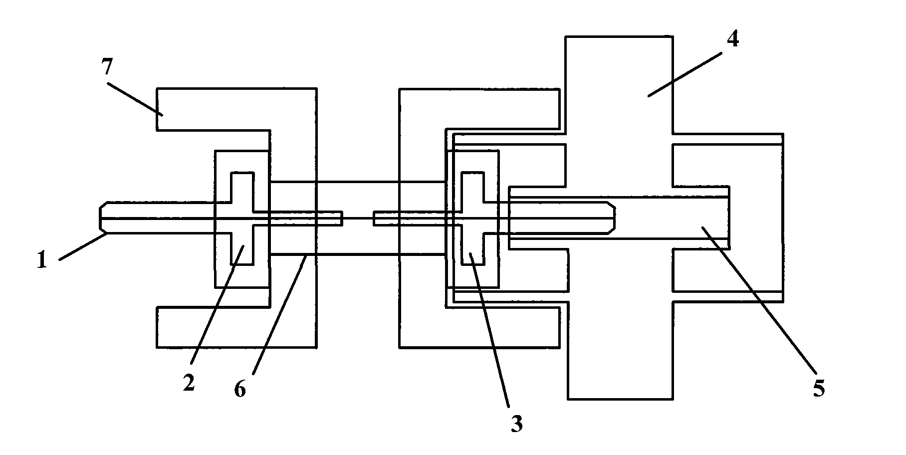
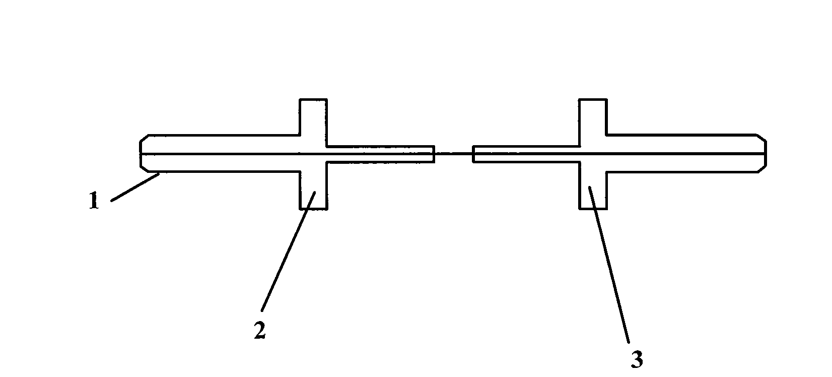
[0021] Such as figure 1 As shown, it is a schematic structural diagram of a fiber optic beam converter according to an embodiment of the present invention. The fiber optic beam converter according to the embodiment of the present invention includes a connector (not shown) and a bare fiber adapter (not shown) that can be connected to an optical instrument The optical fiber ferrule 1 connected to the corresponding optical fiber, such as figure 2 As shown, the optical fiber ferrule 1 includes a first optical fiber ferrule 2 and a second optical fiber ferrule 3, and an ...


PUM


Abstract

The invention provides an optical fiber beam converter, comprising an optical fiber insert core part (1) which is correspondingly connected with an optical instrument connector and a bare fiber adapter, the optical fiber insert core part (1) comprises a first optical fiber insert core (2) and a second optical fiber insert core (3), an optical fiber is respectively integrated in the first optical fiber insert core (2) and the second optical fiber insert core (3), and the optical fibers of the first optical fiber insert core (2) and the second optical fiber insert core (3) are connected. The optical fiber beam converter protects the optical instrument connector and realizes the accurate measurement of spectrum and polarization.

Description

technical field [0001] The invention relates to the technical field of spectrum measurement, in particular to an optical fiber beam converter for realizing the connection between an optical fiber and an optical instrument. Background technique [0002] When measuring spectrum and polarization, in order to realize the connection between optical fiber and optical instruments (such as spectrometers, light sources, etc.), it is necessary to use bare fiber adapters to realize the connection between optical fibers and optical instruments through bare fiber adapters, but if the bare fiber adapters are connected in this way If it is directly connected to the optical instrument, there will be a problem of damaging the optical instrument, thereby causing permanent damage to the optical instrument connector, and the replacement of the optical instrument connector usually requires expensive costs. [0003] At present, the solution in the prior art is to connect the optical instrument co...

Claims


Application Information

Patent Timeline
Patent Type & Authority Patents(China)
IPC IPC(8): G02B6/38G02B6/255G02B6/02
Inventor 徐宏杰郭耀仪张春熹宋凝芳宋镜明罗永锋
Owner BEIHANG UNIV
Why Eureka
Try Eureka