
Method and device for confirming signal-interference-noise radio

A technique for determining SINR and its determination method, which is applied in the field of SINR determination in multi-user wireless communication systems, and can solve the problems of increased system cost, long time, and increased complexity

Inactive Publication Date: 2009-11-04
NTT DOCOMO INC
View PDF3 Cites 6 Cited by
  • Summary
  • Abstract
  • Description
  • Claims
  • Application Information

AI Technical Summary

Problems solved by technology

In this way, within a scheduling period, the complexity of the existing process of determining the SINR is: (2×Nt 3 +Nt 2 +2Nt) complex number operations, it can be seen that the complexity is related to the third-order and second-order exponents of the number of transmitting antennas
Such complexity is acceptable for a system with a single transmit antenna, which is only 5 complex operations; however, when the number of transmit antennas is large, the complexity of the existing scheme will increase sharply, for example, when Nt=2, Its complexity is: (2×2 3 +2 2 +2×2)=24 complex number operations, when Nt=4, its complexity is: (2×4 3 +4 2 +2×4)=152 complex number operations, when Nt=8, then (2×8 3 +8 2 +2×8)=1104 complex number operations
If the above SINR determination scheme is applied to the process of precoding matrix selection or multi-user scheduling, the complexity will increase linearly with the number of precoding matrices or the number of users, so more complex operations need to be performed
[0023] Therefore, the existing SINR determination method has high complexity for the case of multiple transmit antennas
Furthermore, due to the high computational complexity, the multi-user system can only use high-performance equipment, which increases the system cost
In addition, multiple complex calculations will take a long time, so that the equipment that assists in determining the SINR has to perform other tasks at the same time as or after performing these complex calculations, which will cause a long delay in the response to the task and reduce system performance.

Method used


Image

  • Method and device for confirming signal-interference-noise radio
  • Method and device for confirming signal-interference-noise radio
  • Method and device for confirming signal-interference-noise radio

Examples


Embodiment 1

[0083] In this embodiment, before calculating the correlation coefficient sum of each row vector, first calculate the energy of each row vector in the channel response information, and use the calculated energy to normalize each row vector, and then use the normalization result of each row vector Computes the correlation coefficient of the normalized results of each two row vectors. In this embodiment, the correlation coefficient sum of each row vector is the correlation coefficient sum of the normalized result of each row vector.

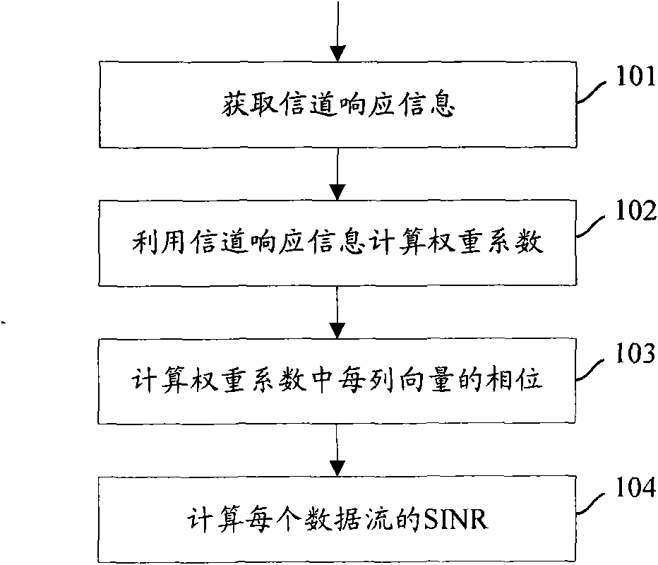
[0084] Figure 4 A detailed flowchart of the SINR determination method in this embodiment is shown, see Figure 4 , in this embodiment, the SINR of each data stream is obtained according to the following steps:

[0085] In step 401, channel response information is obtained.

[0086] Similar to step 101 of the existing method, the channel response information in this step may also be a channel state information matrix or an equivalent channel state...

Embodiment 2

[0119]In this embodiment, the row vector normalization processing of the channel response information in Embodiment 1 is not performed, but the correlation coefficient sum is directly calculated using the row vector in the channel response information, and then each data stream is determined according to the method in step 405 SINR.

[0120] Figure 6 A detailed flowchart of the SINR determination method in this embodiment is shown, see Figure 6 , in this embodiment, the SINR of each data stream is obtained according to the following steps:

[0121] In step 601, channel response information is obtained.

[0122] The channel response information in this step may also be a channel state information matrix or an equivalent channel state information matrix.

[0123] In step 602, the correlation coefficient of each row vector is calculated, and the sum of the correlation coefficients is obtained.

[0124] In this step, the correlation coefficient of each two row vectors in the...


PUM


Abstract

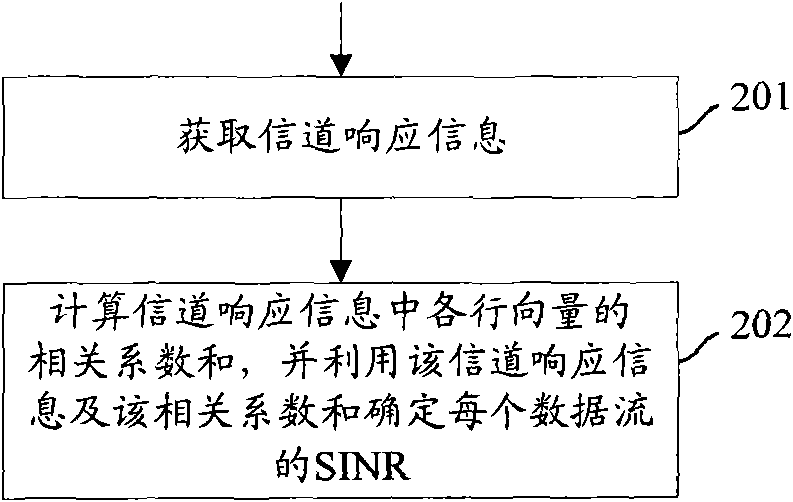
The invention discloses a method and a device for confirming a signal-interference-noise radio (SINR). The method comprises the steps of obtaining channel response information, calculating related coefficient sum of row vectors and confirming the SINR of each data stream by utilizing the channel response information and the related coefficient sum. The device comprises a channel response information acquiring module and a calculating module. The scheme of the invention can effectively lower the complexity for confirming the SINR.

Description

technical field [0001] The present invention relates to a processing technology in a wireless communication system, in particular to a method and device for determining a signal interference noise ratio (signal interference noise ratio, SINR) in a multi-user wireless communication system. Background technique [0002] Compared with the traditional single-input-single-output (SISO) system, multiple antennas at the transmitting end and / or receiving end in a multi-user system can bring space diversity gain and / or space multiplexing gain, So it has better system performance. Therefore, a multi-user system with multiple antennas has become one of the main focuses of the next generation mobile communication system. [0003] In the spatial multiplexing mode, different data streams are distributed on independent spatial channels for transmission. In this way, the simultaneous transmission of multiple data streams greatly increases the throughput of the multi-user system, so that t...

Claims


Application Information

Patent Timeline
Patent Type & Authority Applications(China)
IPC IPC(8): H04B17/00
Inventor 刘竞秀佘小明陈岚田冈秀和
Owner NTT DOCOMO INC
Learn More