Casting method, upper mold assembly, and method for fixing core to the upper mold

A fixing method and assembly technology, which is applied in the field of casting manufacturing, can solve the problems of finished product shape defects, core floating, etc., and achieve the effects of improving productivity, uniform metal structure of castings, and reducing component costs

Active Publication Date: 2009-11-04
SINTOKOGIO LTD +1
View PDF2 Cites 13 Cited by
  • Summary
  • Abstract
  • Description
  • Claims
  • Application Information

AI Technical Summary

Problems solved by technology

However, according to the sand pressure casting process, the upper mold is covered after pouring the lower mold. Therefore, if the core is pre-set on the lower mold before pouring, the core will be damaged due to The buoyancy of the magma floats up, which leads to the problem of shape defects in the finished product
Therefore, only in the sand pressure casting process, if the core is placed in the lower mold as in the past, there will be a problem that the core will float during the pouring process, so it is also necessary to prevent the core in the mold from floating.

Method used


Image

  • Casting method, upper mold assembly, and method for fixing core to the upper mold
  • Casting method, upper mold assembly, and method for fixing core to the upper mold
  • Casting method, upper mold assembly, and method for fixing core to the upper mold

Examples


Embodiment 1

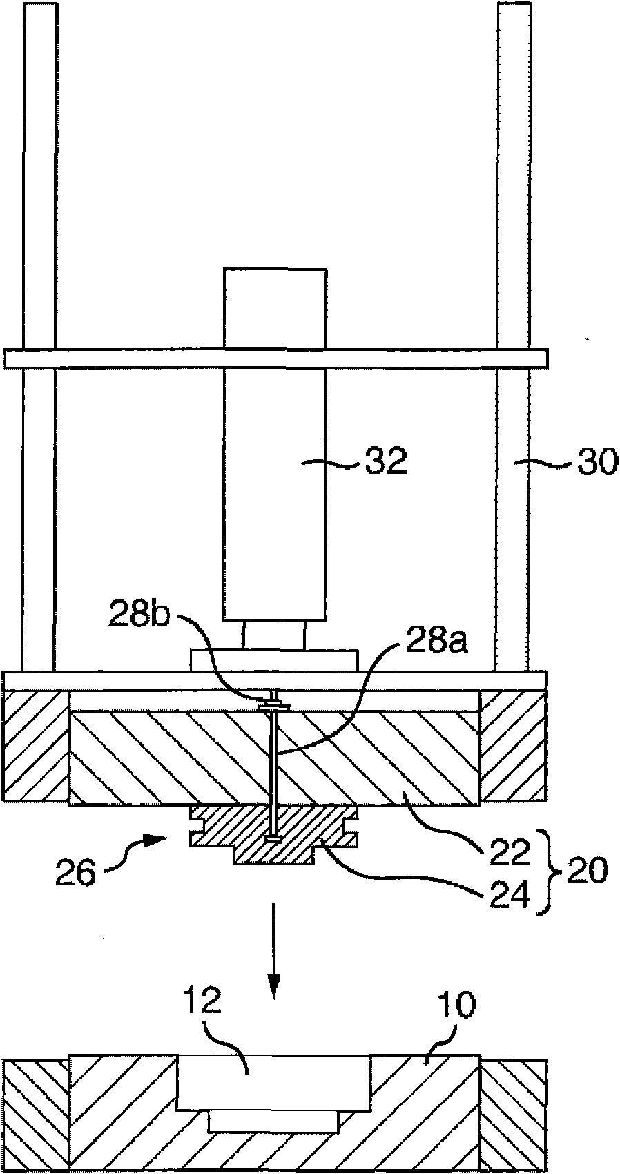
[0057] figure 1 It is a longitudinal cross-sectional view of a casting device including a lower mold 10 and an upper mold assembly 20 schematically showing one embodiment of the present invention.

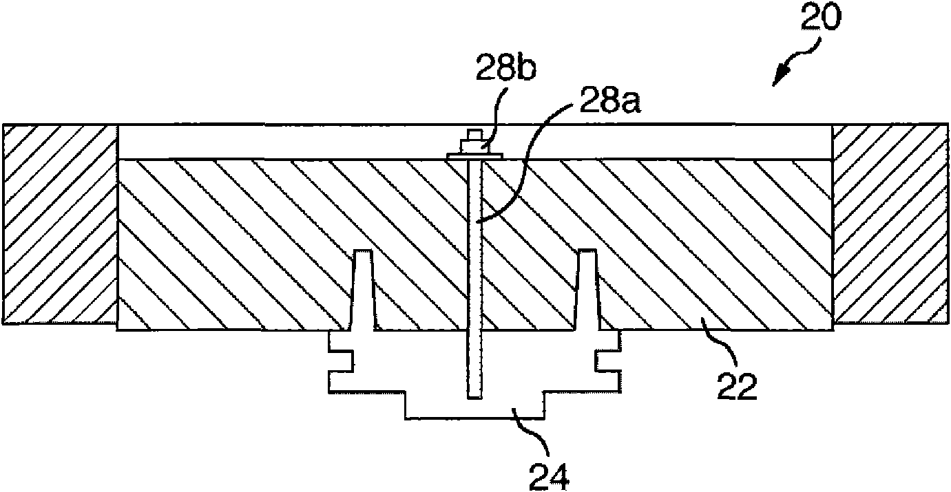
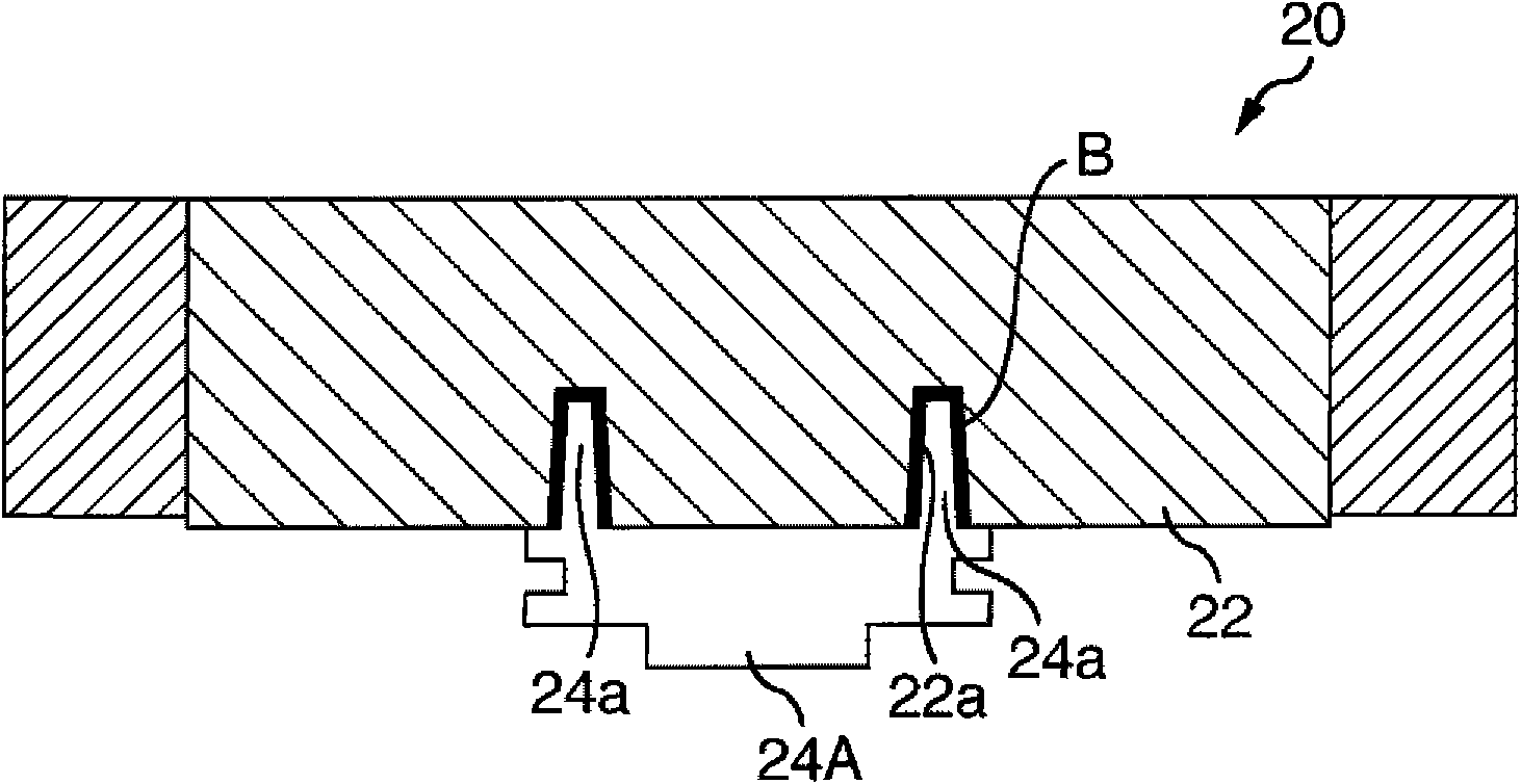
[0058] The lower mold 10 has a recess 12 corresponding to a part of the finished outline shape of the cast product. When the upper mold 22 is matched with the lower mold 10, the recess 12 outlines the cavity of the mold. The upper mold assembly 20 is fixedly assembled on the lower surface of the upper mold 22 with a core 24 forming a protruding portion 26 of the upper mold assembly 20 which, together with the above-mentioned recess 12, defines the finished product. outline shape.

[0059] For making the upper mold assembly 20 through the combination of the upper mold 22 and the core 24, the fixation of the core 24 relative to the upper mold 22 can be carried out by the following bonding methods, that is, mechanical bonding, bonding, etc. Bonding, bonding by friction, and bonding...

Embodiment 2

[0077] The examples described below show examples of joining of the core to the upper mold using frictional force.

[0078] Such as Figure 10 The core 40 placed on the core support 58 of the core mounting device 50 is positioned at a position facing the upper mold 60 positioned above it. The core 40 has a rod-shaped fitting protrusion 42 at the center of the top surface, and the rod-shaped fitting protrusion 42 is pressed into a recessed part 62 formed at the center of the lower surface of the upper mold 60. The friction fit relationship between the parts 62 makes the core 40 installed and fixed on the upper mold 60 .

[0079] The core installation device 50 is mainly composed of the following components, that is, a frame 90 supported on a base (not shown), a guide rod 52 slidably arranged on the frame 90, and a lower part supported by the frame. 90 supports the driving cylinder (pneumatic, hydraulic or electric) device 54 whose upper part is combined with the frame 100 ere...


PUM


Abstract

This invention provides a casting method characterized by comprising the step of fixing a core to an upper mold to provide an upper mold assembly, the step of pouring a minimized amount of molten metal necessary for providing a cast product into a concave in a lower mold, the step of moving the upper mold assembly at a predetermined first speed and lowering the upper mold assembly to a predetermined height just above the surface of the molten metal in the concave, the step of varying the lowering speed of the upper mold assembly from the first speed to the predetermined second speed to further lowering the upper mold assembly from the predetermined height, the step of detecting information about the state of the upper mold assembly in such a state that the upper mold assembly has been superimposed on or lowered toward the lower mold, and the step of stopping of the lowering of the upper mold assembly after the detection that the state information has reached predetermined state information. The core is fixed to the upper mold depending upon a frictional fitting relationship between mechanical means, an adhesive, and a core-side fitting protrusion and the concave fitting part, or the engagement relationship between a core-side engaging projection and molding sand to be tamped down.

Description

technical field [0001] The present invention relates to a method of manufacturing castings (ie, a casting method), an upper mold assembly used in the method, and a method of fixing a core relative to the upper mold. More specifically, it relates to a casting method for obtaining a casting by using a sand pressure casting process, that is, pouring the minimum amount of molten metal required to obtain the casting into a lower mold and fitting the upper mold to the lower mold. Background technique [0002] In metal casting using a sand mold, an upper mold is joined to a lower mold to form a mold cavity, and molten metal (slurry) is poured into the cavity to produce a casting. In this widely used casting method, it is necessary and indispensable to provide a flow path of the pouring metal called a casting plan, which is not related to the shape of the product. The purpose is to control the flow of the pouring metal and prevent it The mixing of pure substances and gases prevents...

Claims


Application Information

Patent Timeline
Patent Type & Authority Applications(China)
IPC IPC(8): B22D23/00B22D18/02B22C9/02
CPCB22D18/02B22C21/14B22C9/108B22D23/00
Inventor 桥本邦弘岩崎顺一羽片丰釜坂刚史
Owner SINTOKOGIO LTD
Why Eureka
Try Eureka