Wiper arm

A technology of wiper arm and fixing parts, applied in the field of wiper arm, can solve the problems of the loss of the support force of the wiper arm, the shortening of the spring length, etc., and achieve the effect of saving materials

Active Publication Date: 2009-11-04
ROBERT BOSCH GMBH
View PDF0 Cites 0 Cited by
  • Summary
  • Abstract
  • Description
  • Claims
  • Application Information

AI Technical Summary

Problems solved by technology

This results in a loss of support for the wiper arm because the spring length of the spring embedded in the sheet metal is shortened
In addition, dimples and burrs

Method used


Image

  • Wiper arm
  • Wiper arm
  • Wiper arm

Examples


Embodiment Construction

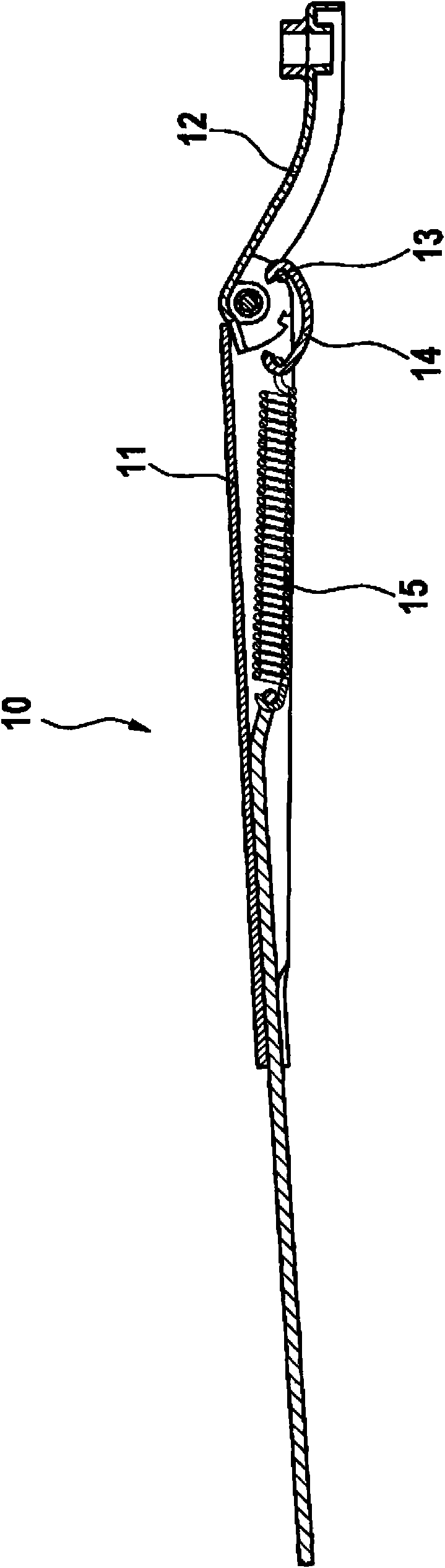
[0027] figure 1 Wiper arm 10 is shown with hinged part 11 and fastening part 12 . The articulation part 11 is articulated on the fastening part 12 , so that a wiper blade, not shown in detail here, is pivotably arranged on the wiper arm 10 . In this way, the wiper blade can be pivoted away from the window glass and can be pivoted into engagement on the window glass.

[0028] A C-shaped hook 14 is hung at the bolt bar 13, a spring 15 is hung in the hook, and the spring 15 is hung at the hinge 11 again in the same way.

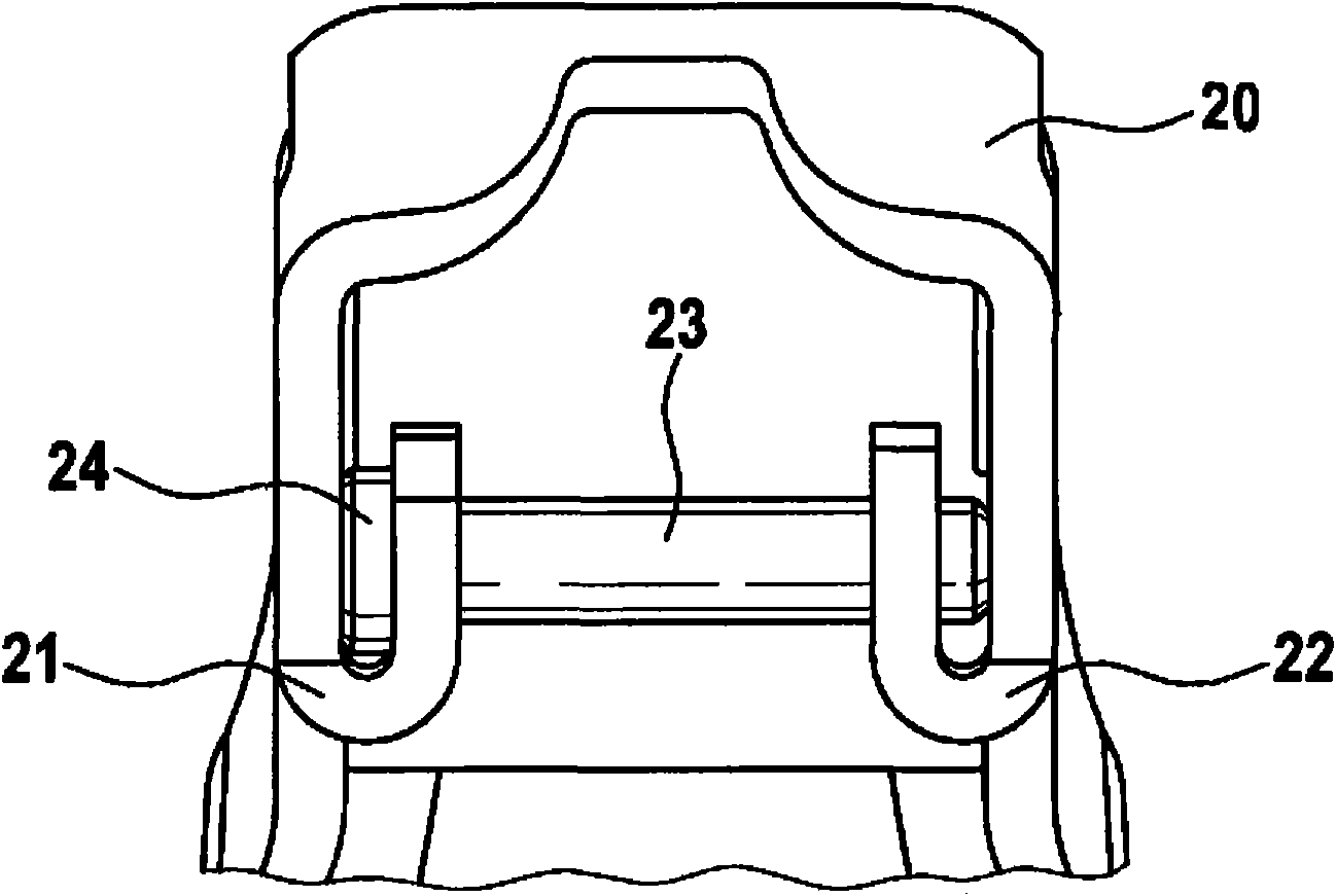
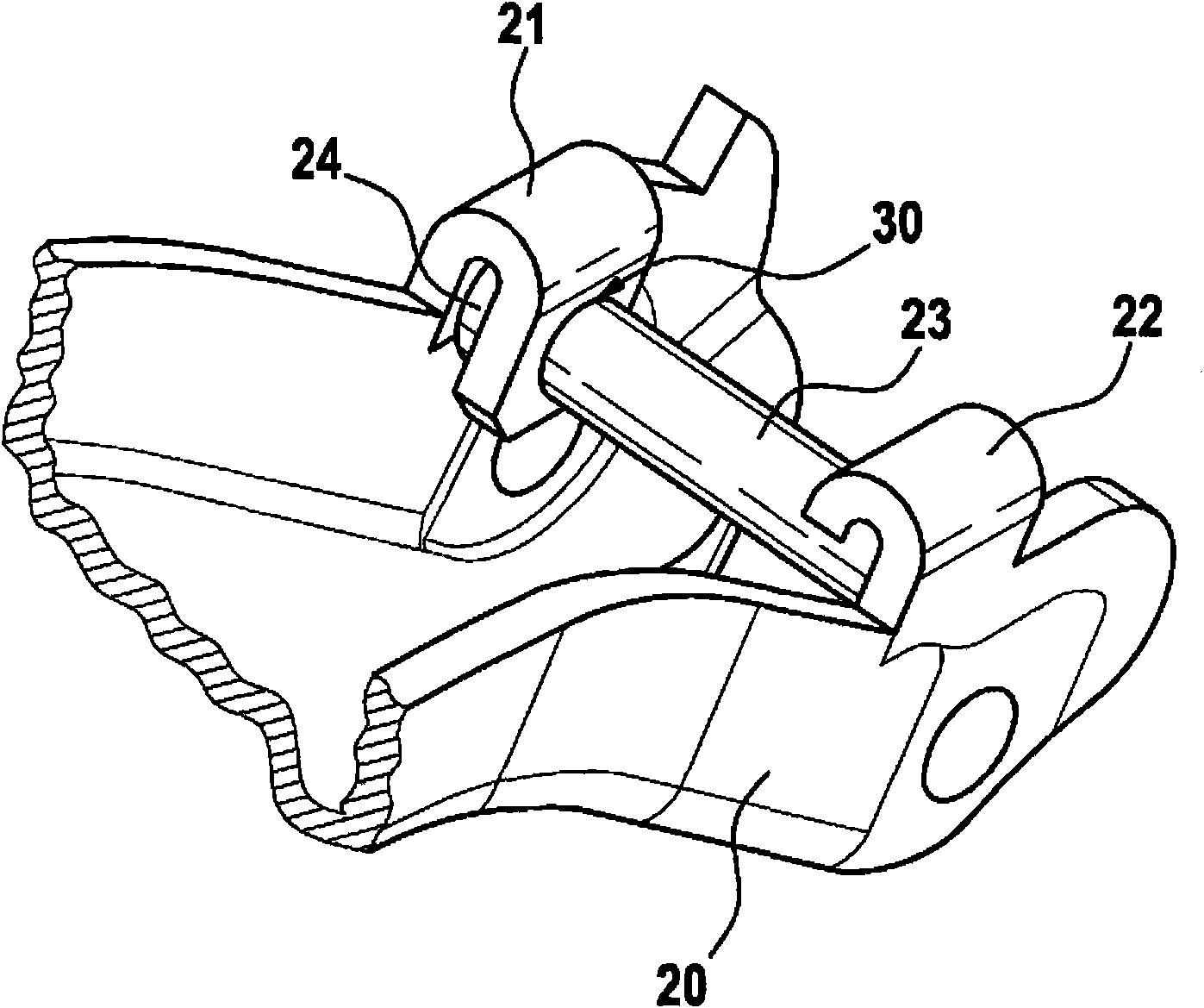
[0029] figure 2 A fastening part 20 with two webs 21 and 22 and a pin 23 is shown. The webs 21 and 22 are bent towards the inside of the fixing part 20 . As a result, the bolt rod 23 has a relatively short length. Due to the relatively short length of the pin 23 , deflections can be reduced and thus a maximum bearing force of the wiper arm 10 can be ensured.

[0030] Tab 21 has a through hole 30 (see image 3 ), the bolt rod 23 passes through the through...


PUM

PropertyMeasurementUnit
Diameteraaaaaaaaaa

Abstract

The invention relates to a wiper arm of a window wiping device having an attachment part (20) which is manufactured from sheet metal. In the sheet metal attachment parts of the generic type, a spring hook fastening element which is likewise manufactured from sheet metal and into which, however, in the course of time a spring digs is frequently used. This results in a loss of the supporting force of the wiper arm. In order to prevent this in future, the attachment part (20) is provided according to the invention with two clips (21, 22) for receiving a bolt (23).

Description

technical field [0001] The invention relates to a wiper arm of a wiper device with a fastening element. Background technique [0002] Following the development from cast mountings to sheet metal mountings, with this development a spring support made of sheet metal for receiving the spring is also provided on the sheet metal mounting. However, with a spring carrier made of sheet metal, it can happen that the spring becomes embedded in the sheet metal of the spring carrier over time. This results in a loss of support for the wiper arm, since the spring length of the spring embedded in the sheet metal is shortened. In addition, dimples and burrs on the surface of the spring carrier resulting from the production of the spring carrier can lead to the generation of undesired noises during operation of the wiper arm. SUMMARY OF THE INVENTION [0003] It is therefore the object of the present invention to improve a wiper arm of the type mentioned at the outset in such a way that...

Claims


Application Information

Patent Timeline
IPC IPC(8): B60S1/34
CPCB60S1/3438B60S1/3468
Inventor S·迈耶A·斯米特
Owner ROBERT BOSCH GMBH
Why Eureka
Try Eureka