Injection device

An injection device and syringe technology, applied in the field of medical devices, can solve problems such as difficult high-precision control, complex structure, and difficult miniaturization, and achieve the effect of simple structure and high injection accuracy

Inactive Publication Date: 2009-11-11
JOHNSON ELECTRIC SHENZHEN
View PDF2 Cites 26 Cited by
  • Summary
  • Abstract
  • Description
  • Claims
  • Application Information

AI Technical Summary

Problems solved by technology

[0003] However, the above-mentioned ordinary injection device using a stepping motor has a complex structure, is difficult to miniaturize, and is difficult to control with high precision.

Method used


Image

  • Injection device
  • Injection device
  • Injection device

Examples


Embodiment Construction

[0015] In order to make the technical problems, technical solutions and beneficial effects to be solved by the present invention clearer, the present invention will be further described in detail below with reference to the accompanying drawings and embodiments. It should be understood that the specific embodiments described herein are only used to explain the present invention, but not to limit the present invention.

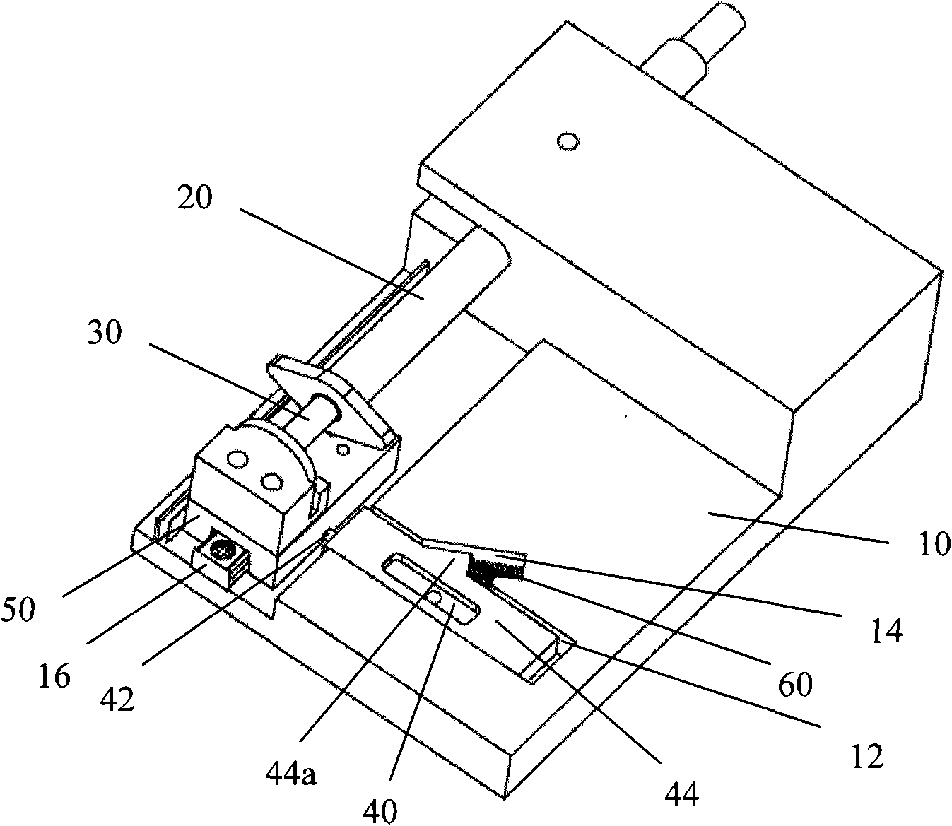
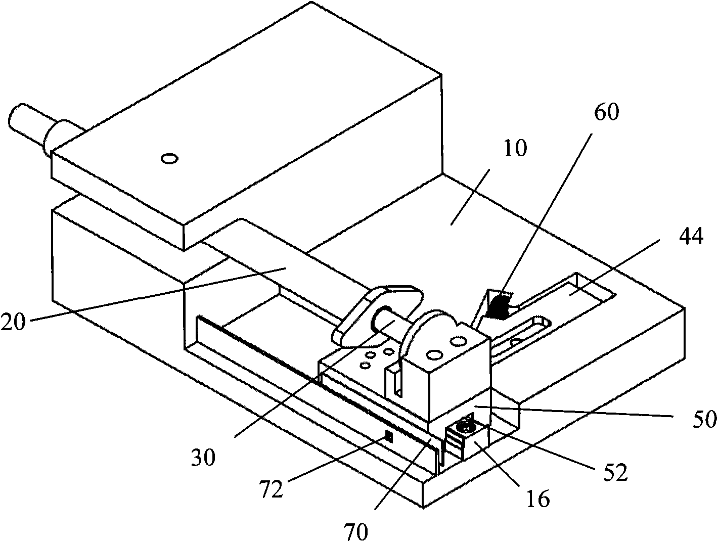
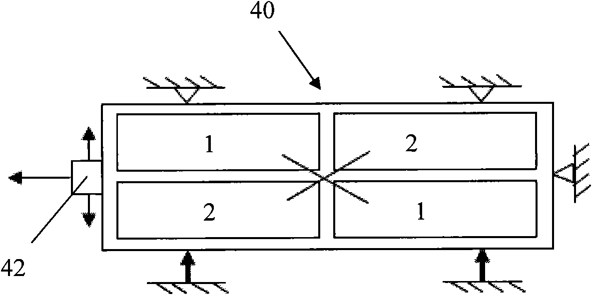
[0016] The injection device of the present invention includes a base; a syringe kit comprising a syringe mounted on the base and a push rod slidably inserted into one end of the syringe; a motor head mounted on the base A piezoelectric motor; and a transmission mechanism connected between a motor head of the piezoelectric motor and a push rod, when the piezoelectric motor is excited, the motor head is selectively driven in one of two opposite directions The transmission mechanism selectively pushes the push rod forward or backward.

[0017] Figure 1 to Figur...


PUM


Abstract

The invention provides an injection device which comprises a base, an injector kit, a piezoelectric motor and a driving mechanism, wherein the injector kit comprises a syringe arranged on the base anda push rod capable of being movably inserted into one end of the syringe; the piezoelectric motor is arranged on the base and provided with a motor head; the driving mechanism is connected between the motor head of the piezoelectric motor and the push rod; and when the piezoelectric motor is excited, the motor head selectively drives the driving mechanism along one of two opposite directions so as to selectively push the push rod to advance or retreat. The injection device has simple structure. Because the displacement of the piezoelectric motor under the action of a serial drive pulse is ofa nanometer level, higher injection precision can be guaranteed. Because electromagnetic force is not utilized to drive, the injection device is more suitable for some special occasions such as strongmagnetic fields or electromagnetic sensitivity, and the like.

Description

technical field [0001] The invention relates to the field of medical instruments, in particular to an injection device. Background technique [0002] The ordinary injection device generally includes a stepping motor, a deceleration mechanism, a screw rod, a nut, a guide rod and a needle tube push seat. After the rotation of the stepping motor is decelerated by the deceleration device, it is transmitted to the screw rod. The screw rod cooperates with the nut, and the guide rod and the nut Fixed connection, the needle tube push seat is connected with the guide rod, so that the movement can be transmitted to the needle tube push seat through the guide rod connected with the nut to push the needle tube. [0003] However, the above-mentioned common injection device using a stepping motor has a complicated structure, which is difficult to miniaturize and control with high precision. SUMMARY OF THE INVENTION [0004] In order to solve the above technical problems, the present in...

Claims


Application Information

Patent Timeline
Patent Type & Authority Applications(China)
IPC IPC(8): A61M5/20A61M5/31
Inventor 石斌李红李兴全张勇刚
Owner JOHNSON ELECTRIC SHENZHEN
Why Eureka
Try Eureka