Shell course rolling technology and rolling equipment thereof

A rolling equipment and barrel section technology, which is applied in metal rolling and other directions, can solve the problems of instability of the rolling mill, tearing, poor mechanical properties of the barrel section being processed, etc., to improve product quality, expand the size range, and be difficult to stretch. The effect of defects

Active Publication Date: 2009-11-11
CHINA FIRST HEAVY IND +1
View PDF0 Cites 9 Cited by
  • Summary
  • Abstract
  • Description
  • Claims
  • Application Information

AI Technical Summary

Problems solved by technology

[0004]There are unavoidable defects in processing barrel joints in the form of single drive
First of all, the rolling torque in the form of single drive is small, resulting in a small rolling force applied by the roll to the processed barrel section, and the compression of the barrel section during the rolling process is relatively small; when processing a barrel section with a small wall thickness, Since the wall thickness has little influence on the stress transfer, the single drive will not have a great influence on the quality of the finished product of the barrel joint, but when processing a barrel joint with a large wall thickness, the transfer of the tensile stress is affected by the wall thickness, which will make the The inner and outer surfaces of the barrel joint are torn, and the single drive cannot process larger barrel joints, which limits the scale of the barrel joint to be processed
Secondly, during the rolling process of the single-drive method, the deformation of the inner wall of the processed barrel section (that is, the contact surface with the passive inner work roll) is tensile deformation. When the stress is close to the strength limit, defects are prone to occur, resulting in the processed The mechanical performance of the barrel joint is poor, which affects the quality of the finished barrel joint
In addition, in the single-drive mode, the torque difference between the two work rolls to the rolling mill is relatively large, which will generate an overturning moment to the rolling mill, making the rolling mill tend to be unstable
It can be seen that the product quality and product scale of the barrel joints obtained by the existing processing methods are not ideal.

Method used


Image

  • Shell course rolling technology and rolling equipment thereof
  • Shell course rolling technology and rolling equipment thereof
  • Shell course rolling technology and rolling equipment thereof

Examples


Embodiment Construction

[0054] The core of the present invention is to provide a rolling method of the barrel joint, which improves the rolling force of the rollers on the barrel joint and overcomes the stress defect on the inner wall of the barrel joint, thereby improving the product scale and product quality of the barrel joint. Another core of the present invention is to provide a rolling equipment that applies the above-mentioned method to process barrel segments.

[0055] In order to enable those skilled in the art to better understand the solutions of the present invention, the present invention will be further described in detail below in conjunction with the drawings and specific embodiments.

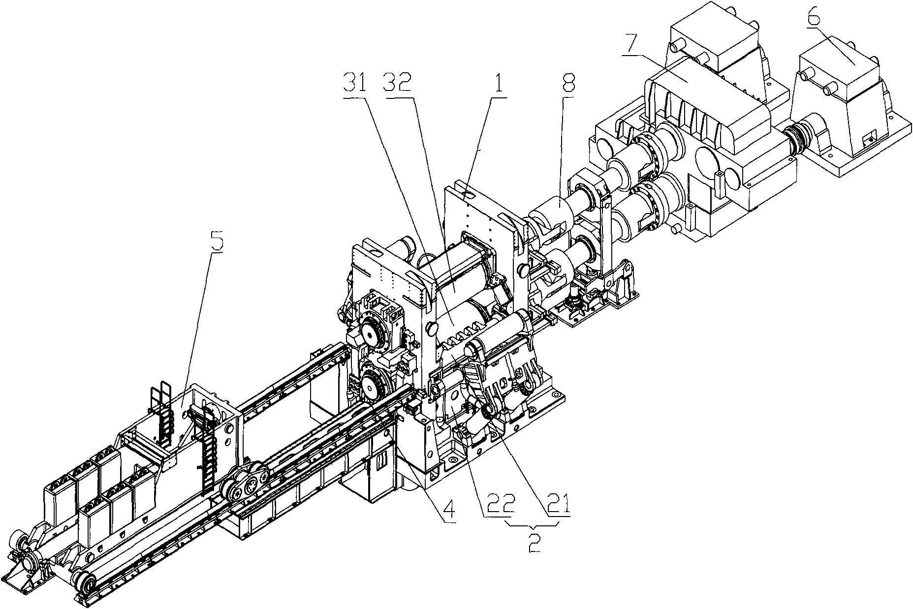
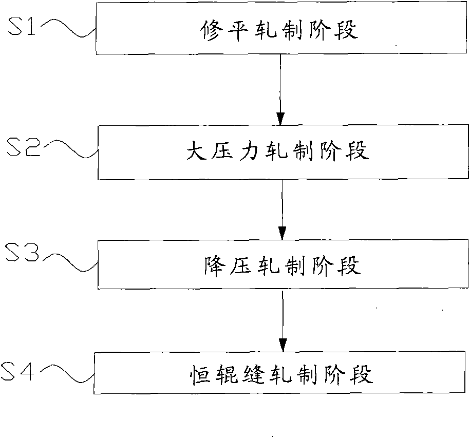
[0056] Please refer to figure 1 and figure 2 , figure 1 Schematic diagram of the structure of the barrel section rolling equipment provided by the present invention; figure 2 It is a schematic flow chart of a specific embodiment of the barrel joint processing method provided by the present inventi...


PUM


Abstract

The invention discloses a shell course rolling method, which is characterized in that a first roller and a second roller respectively extrude the inner wall and the outer wall of the shell course. The core lies in that in the process of rolling, the first roller and the second roller are driven by driving devices to rotate. The invention also discloses shell course rolling equipment, comprising the first roller and the second roller; the first roller and the second roller are all drive rollers driven by the driving devices. The method and equipment discloses by the invention are used for rolling the shell course in a manner of double roller driving, thereby overcoming the defect of surface anti-fatigue stress on the inner wall of the shell course and improving the mechanical property of the finished shell course product.

Description

technical field [0001] The invention relates to the technical field of metal rolling, in particular to a barrel segment rolling process. The present invention also relates to a rolling plant that can process barrel segments using the above-mentioned process. Background technique [0002] With the rapid development of my country's economic construction, barrel joints of various sizes and specifications are more and more widely used in various fields of industrial production. The increase in demand has led to the improvement of the processing technology of the barrel joint and the improvement of the processing equipment used in conjunction with the process. [0003] Many production units use rolling mills to process barrel joints. This kind of rolling mill generally mainly includes drive motors, outer work rolls, inner work rolls and other components. rolling process. At present, the single-drive method is mostly used to process the barrel joint, that is, the outer work ro...

Claims


Application Information

Patent Timeline
Patent Type & Authority Applications(China)
IPC IPC(8): B21B1/00
CPCB21B5/00
Inventor 吴生富周晓平刘刚马克王光儒付环宇
Owner CHINA FIRST HEAVY IND
Why Eureka
Try Eureka