
Tail gas removing device with pressure boost and oxygen increase by strong force for vehicle

A powerful, exhaust technology, applied in the direction of machine/engine, mechanical equipment, combustion engine, etc., can solve problems such as non-ideal

Inactive Publication Date: 2009-11-11
上海徕普太阳能科技有限责任公司
View PDF0 Cites 0 Cited by
  • Summary
  • Abstract
  • Description
  • Claims
  • Application Information

AI Technical Summary

Problems solved by technology

[0002] Various schemes about automobile fuel saving and tail gas removal are a lot, but all are not ideal, for this reason the inventor has researched and developed "vehicle powerful pressurization oxygenation and tail gas removal device"

Method used


Image

  • Tail gas removing device with pressure boost and oxygen increase by strong force for vehicle
  • Tail gas removing device with pressure boost and oxygen increase by strong force for vehicle
  • Tail gas removing device with pressure boost and oxygen increase by strong force for vehicle

Examples


Embodiment 1

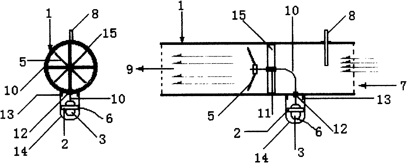
[0013] exist figure 1 Middle: (1) round pipe, (2) motor fixing ring frame, (3) motor, (4) motor bearing, (5) fan blade, (6) motor wire, (7) air purifier interface, (8) Oxygen interface, (9) cylinder intake interface.

[0014] In the figure: the (2) motor fixing ring frame is connected in (1) round tube; the (3) motor, (4) motor bearing, (5) fan blade, (6) are connected in (2) motor fixing ring frame ) motor wire; (1) one end of the round pipe is (7) air cleaner interface, and the other end is (9) cylinder air intake interface; (8) oxygen interface is connected outside (1) round pipe.

Embodiment 2

[0015] Embodiment two: (1) round pipe, (2) motor fixed ring frame, (3) motor, (4) motor bearing, (5) fan blade, (6) motor wire, (7) air cleaner interface, ( 8) Oxygen interface, (9) Cylinder intake interface, (10) Flexible shaft, (11) Fan blade flexible shaft, (12) Motor bearing, (13) Motor housing interface, (14) Motor housing, (15) Bearing Fixed circle frame.

[0016] exist figure 2 Middle: The (15) bearing fixing ring frame is connected in (1) round pipe; the (11) fan blade soft shaft and (5) fan blade are connected in (15) bearing fixing ring frame; (1) one end of the round pipe It is (7) air purifier interface, and the other end is (9) air intake interface of cylinder; (8) oxygen interface and (13) motor outer cover interface are connected outside (1) round pipe; on (13) motor outer cover interface (12) motor bearing and (10) flexible shaft are connected with (3) motor; (3) motor is fixed in (2) motor fixing ring frame; (2) motor fixing ring frame is fixed in (14) moto...

Embodiment 3

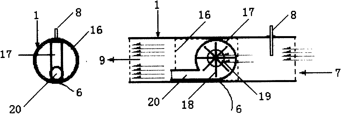
[0018] exist image 3 Middle: (1) round tube, (6) motor wire, (7) air cleaner port, (8) oxygen port, (9) cylinder air intake port, (13) motor cover port, (16) axial fan fixation Frame, (17) axial flow fan, (18) axial flow fan fan blade, (19) purification gas inlet, (20) high-pressure discharge port.

[0019] In the figure: (16) axial flow fan fixed frame is connected in (1) round pipe; (17) axial flow fan, (20) high pressure outlet, (6) are connected in (16) axial flow fan fixed frame Electric motor electric wire; One end of (1) round pipe is (7) air purifier interface, and the other end is (9) cylinder intake port; (8) oxygen interface is connected outside (1) round pipe.


PUM


Abstract

The invention relates to a tail gas removing device with pressure boost and oxygen increase by strong force for vehicles, comprising a circuit pipe, a motor fixing ring frame, a motor, a motor bearing, a fan blade, a motor wire, an air purifier interface, an oxygen interface, a cylinder air-intake interface, a flexible shaft, a fan blade flexible shaft, a motor bearing, a motor shell interface, a motor shell, a bearing fixing ring frame, an axial-flow fan fixing frame, an axial-flow fan, an axial-flow fan blade, a purified air inlet, a high air pressure exhaust opening and a pipe type blade static mixer. The tail gas removing device can save 20-40 percent of oil when being used on various oil-fired engines, can remove all tail gases, is an energy-saving and environmental-friendly type product and especially has very extensive market prospect under the condition of less and less crude oil.

Description

Technical field: [0001] Automobile fuel-saving and exhaust gas-saving energy-saving and environmental protection products. Background technique: [0002] Various schemes about fuel saving and tail gas removal for automobiles are a lot, but all are not ideal, for this reason the inventor has researched and developed "vehicle powerful pressurization oxygenation and tail gas removal device". Invention content: [0003] The "vehicle powerful pressurized oxygen-increasing exhaust gas removal device" of the present invention is connected to the middle position of the air inlet of the air cleaner of the automobile and the air inlet of the cylinder (in the original colloid connecting pipe or directly connected), and its purpose is to increase Large intake pressure, increased air flow and increased oxygen supply can fully burn, save fuel and eliminate exhaust gas (all water is discharged), and oxygen can be supplemented in anoxic areas. The technical solution adopted by the presen...

Claims


Application Information

Patent Timeline
Patent Type & Authority Applications(China)
IPC IPC(8): F02B33/40
Inventor 陈绍勇
Owner 上海徕普太阳能科技有限责任公司
Learn More