Fan and flow-guided structure thereof

A fan and fan blade technology, applied in the field of fans that can change the air flow direction, can solve the problems of low efficiency, loud noise, and low air output, and achieve the effect of large air output, low noise, and high heat dissipation efficiency

Inactive Publication Date: 2009-11-11
DELTA ELECTRONICS INC
View PDF0 Cites 8 Cited by
  • Summary
  • Abstract
  • Description
  • Claims
  • Application Information

AI Technical Summary

Problems solved by technology

[0006] However, compared with the axial flow fan, although the centrifugal fan can achieve the purpose of ch

Method used


Image

  • Fan and flow-guided structure thereof
  • Fan and flow-guided structure thereof
  • Fan and flow-guided structure thereof

Examples


Embodiment Construction

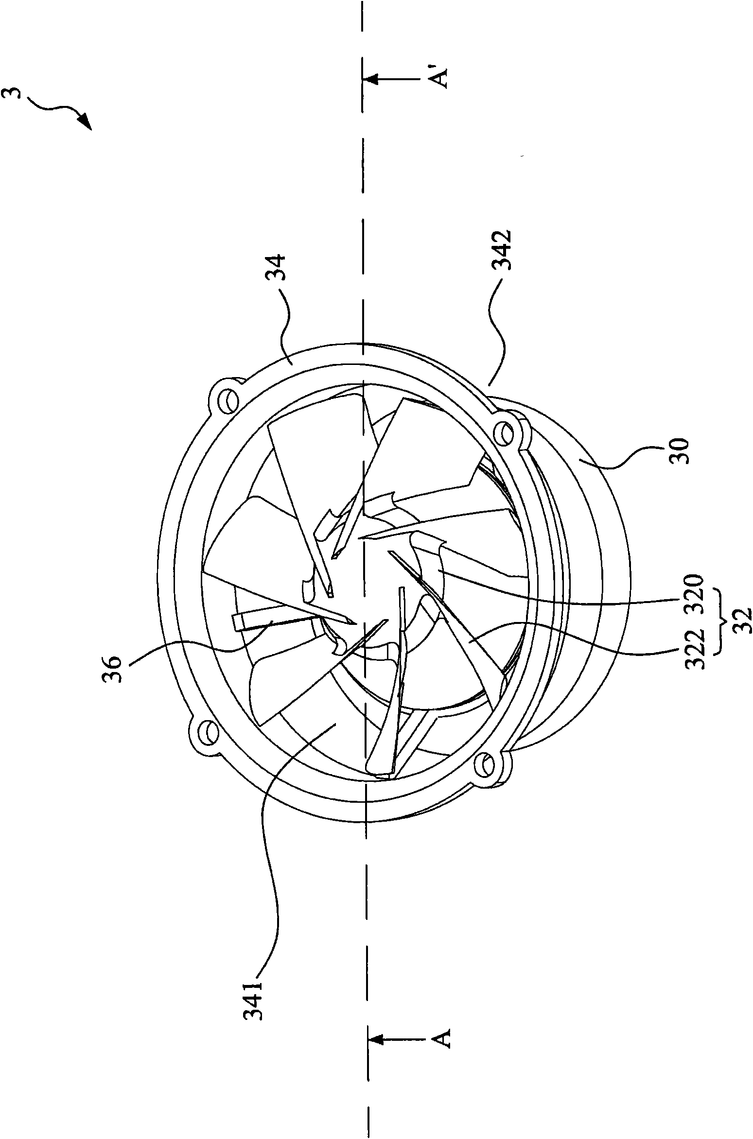
[0037] Please also refer to image 3 and Figure 4 as shown, image 3 is a perspective view of the first embodiment of the present invention, Figure 4 is along image 3 Sectional view of section line A-A' in the middle. As shown in the figure, the fan 3 of the present invention includes a flow guide structure 30 , an impeller 32 and a guide ring 34 .

[0038] The outer diameter of the flow guide structure 30 gradually expands from the top of the flow guide structure 30 to the bottom of the flow guide structure 30 , so that the outer ring surface of the flow guide structure 30 forms at least one curved surface. The impeller 32 is disposed above the flow guiding structure 30 , and the impeller 32 has a hub 320 and a plurality of fan blades 322 . The fan blade 322 is disposed on the outer ring surface of the hub 320 , and the hub 320 is provided with a motor (not shown in the figure), and the outer diameter of the hub 320 gradually expands from the top of the hub 320 to the...


PUM


Abstract

The invention discloses a fan and a flow-guided structure thereof. The fan comprises a flow-guided structure, an impeller and a guide ring, wherein the external diameter of the flow-guided structure gradually enlarges to the bottom of the flow-guided structure from the top of the flow-guided structure; the impeller is arranged above the flow-guided structure and comprises a plurality of fan blades; the guide ring is connected to the flow-guided structure by at least one connecting piece, and a scheduled distance is arranged between the inside ring surface of the guide ring and the outer end edges of the fan blades; and the top of the guide ring is provided with an air inlet, and an air outlet is formed between the bottom edge of the guide ring and the outside ring surface of the bottom of the flow-guided structure. When the impeller is rotated, air flows in from the air inlet, flows along the outside ring surface of the flow-guided structure and flows out from the air outlet, and a direction of the air flowing out from the air outlet is different from a direction of the air flowing in from the air inlet.

Description

technical field [0001] The invention relates to a fan, in particular to a fan capable of changing the direction of air flow. Background technique [0002] With the continuous improvement of the performance of electronic devices, cooling devices or cooling systems have become one of the indispensable equipment in current electronic devices, because if the heat energy generated by electronic devices is not dissipated properly, the performance will deteriorate at least, and the serious It may cause burning of the electronic device. Heat sinks are even more important for microelectronic components (such as integrated circuits, ICs), because with the increase in integration and the advancement of packaging technology, the area of ​​integrated circuits is continuously shrinking, and the heat energy accumulated per unit area is also decreasing. Relatively higher, so heat dissipation devices with high heat dissipation efficiency have been actively researched and developed by the el...

Claims


Application Information

Patent Timeline
IPC IPC(8): F04D29/54F04D29/34F04D29/00F04D19/00
Inventor 许家铭张楯成
Owner DELTA ELECTRONICS INC
Why Eureka
Try Eureka