System and method for measuring compact range antenna by three reflectors

A three-mirror, antenna measurement technology, applied in the direction of antenna radiation pattern, electromagnetic field characteristics, etc., to achieve the effect of compact structure, high isolation, and measurement frequency bandwidth

Active Publication Date: 2009-11-11
BEIJING UNIV OF POSTS & TELECOMM
View PDF0 Cites 27 Cited by
  • Summary
  • Abstract
  • Description
  • Claims
  • Application Information

AI Technical Summary

Problems solved by technology

Due to the wide application of electromagnetic waves with frequencies above...

Method used


Image

  • System and method for measuring compact range antenna by three reflectors
  • System and method for measuring compact range antenna by three reflectors
  • System and method for measuring compact range antenna by three reflectors

Examples


Embodiment Construction

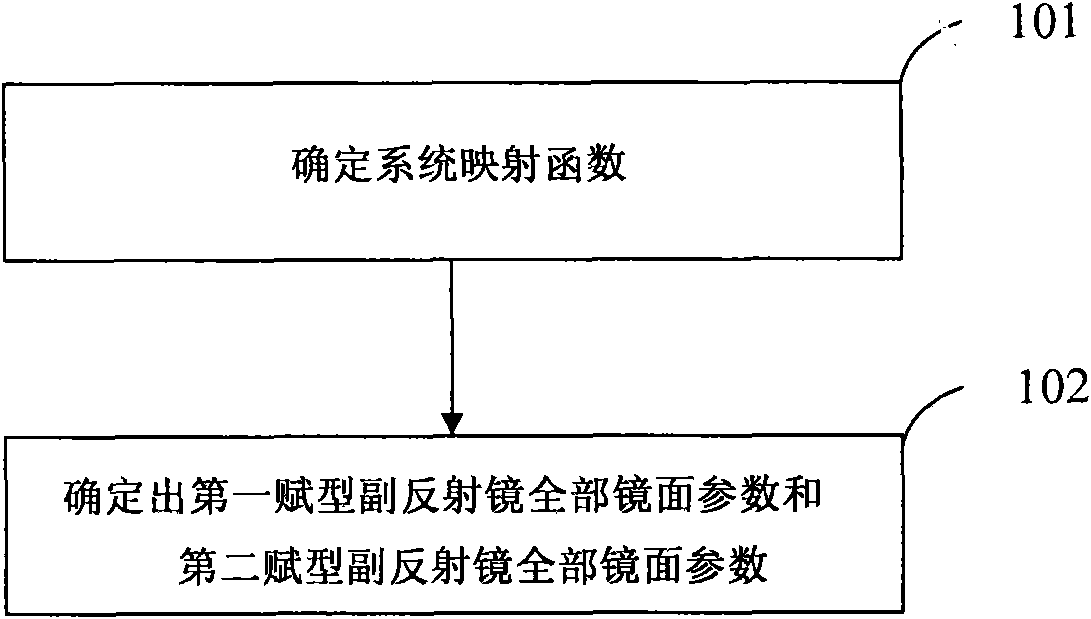
[0025] In order to make the object, technical solution and advantages of the present invention more clearly, the present invention will be further described in detail below in conjunction with the accompanying drawings and specific embodiments.

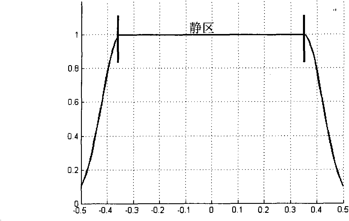
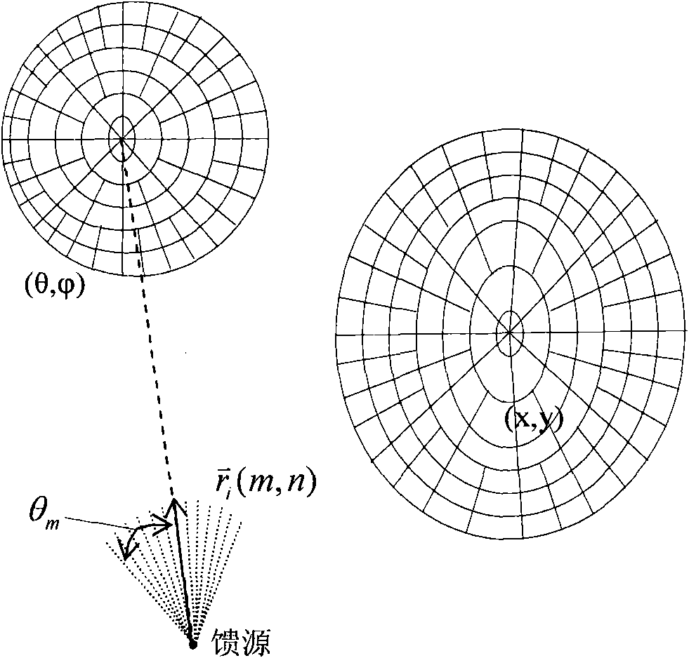
[0026] In the embodiment of the present invention, in the three-mirror compact field antenna measurement system, the compact field system consists of a feed source and three reflectors. The three reflectors include a large-aperture primary reflector with a certain shape and two shaped secondary reflectors. The electromagnetic wave emitted by the feed source is reflected and focused by the first shaped sub-reflector and the second shaped sub-reflector, and finally emerges from the main reflector to obtain an output field with a flat center and steeply falling edges, as shown in figure 1 , the flat waveform area in the middle is the quiet zone suitable for measuring antennas.

[0027] The shape of the primary reflector is a sphere, ell...


PUM


Abstract

A method for measuring a compact range antenna by three reflectors comprises the following steps of: determining a system mapping function according to the distribution of a feed source field and the distribution of a system outlet field; tracking and analyzing the electromagnetic wave emitted by the feed source by adopting a dynamic waveband tracking theory; and determining all mirror surface parameters of a first forming auxiliary reflector and a second forming auxiliary reflector by the system mapping function, the feed source field wavefront parameters and the main reflector surface parameters. The embodiment of the invention also discloses a system for measuring compact range antenna by three reflectors. The system and the method can be applicable to the feed source higher than 300GHz, and lead the system outlet field to have large quiet zone utilization coefficient (achieving more than 70%), high cross polarization isolation degree, compact structure and wide measurement frequency bands.

Description


Claims


Application Information

Patent Timeline
IPC IPC(8): G01R29/08G01R29/10
Inventor 麦源俞俊生陈晓东刘绍华刘小明王宇锋徐亮苏汉生魏钦刚汪玮
Owner BEIJING UNIV OF POSTS & TELECOMM
Why Eureka
Try Eureka