Solar tracking device

A technology of solar tracking and solar panels, applied in the direction of photovoltaic power generation, photovoltaic modules, electrical components, etc., can solve the problems of poor marketing and application effects, high manufacturing and installation costs, and limited scope of application, and achieve accurate adjustment, The effect of height reduction and production cost reduction

Inactive Publication Date: 2009-11-11
江苏白兔科创新能源股份有限公司
View PDF3 Cites 22 Cited by
  • Summary
  • Abstract
  • Description
  • Claims
  • Application Information

AI Technical Summary

Problems solved by technology

[0002] The current method of solar photovoltaic power generation is to let sunlight shine on a fixed flat-panel solar panel tilted at a certain angle, and the power generation efficiency is low; while the tracking-type flat-panel system is controlled by a single unit, which has a large area and uses a lot of materials; there are also panels and orientations. The execution motor system is relatively high from its installation plane, and the wind load is relatively large. It must be installed with basic engineering and construction machinery during installation, which is costly for manufacturing and installation, and the scope of application is limited, especially not suitable for use on the roof. Market promotion and the app doesn't work well

Method used


Image

  • Solar tracking device
  • Solar tracking device
  • Solar tracking device

Examples


Embodiment 1

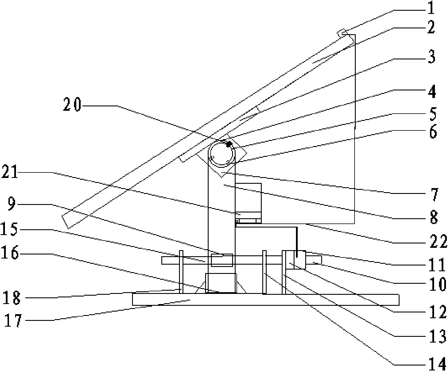
[0024] Such as figure 1 and figure 2 As shown, the solar tracking device includes a base 17, a main support frame 8, an azimuth actuator motor 11 with an azimuth reducer 12, an azimuth drive shaft 10, a pitch rotation shaft 5, a solar panel assembly 2, and a battery panel The component mounting frame 3 and the main controller 21, the solar cell panel assembly 2 are fixedly installed on the cell panel assembly mounting frame 3, and the cell panel assembly mounting frame 3 is fixed on the pitch angle rotating shaft 5 through the connecting plate 7, and the solar cell panel assembly 2 is vertically installed with a light sensor receiver 1, and the main controller 21 is connected with the azimuth actuator motor 11 and the light sensor receiver 1 through the control connection line 22; the pitch angle rotation shaft 5 is sleeved with a pitch angle rotation sleeve 4 , the pitch angle rotation shaft sleeve 4 circumferential surface is provided with three pitch angle adjustment hole...

Embodiment 2

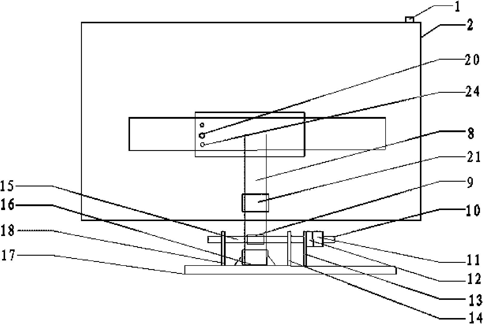
[0026] Such as image 3 and Figure 4 As shown, the solar tracking device includes a base 17, a main support frame 8, an azimuth actuator motor 11 with an azimuth reducer 12, an azimuth drive shaft 10, a pitch rotation shaft 5, a solar panel assembly 2, and a battery panel The component mounting frame 3 and the main controller 21, the solar cell panel assembly 2 are fixedly installed on the cell panel assembly mounting frame 3, and the cell panel assembly mounting frame 3 is fixed on the pitch angle rotating shaft 5 through the connecting plate 7, and the solar cell panel assembly 2. A current sensing receiver 19 is installed inside, and the current sensing receiver 19 is inductively connected with the panel connection line 25 of the solar panel assembly 2; the main controller 21 communicates with the azimuth execution motor 11 and the current sensing The receiver 19 is connected; the pitch angle rotation shaft 5 is sleeved with a pitch angle rotation shaft sleeve 4, and the ...

Embodiment 3

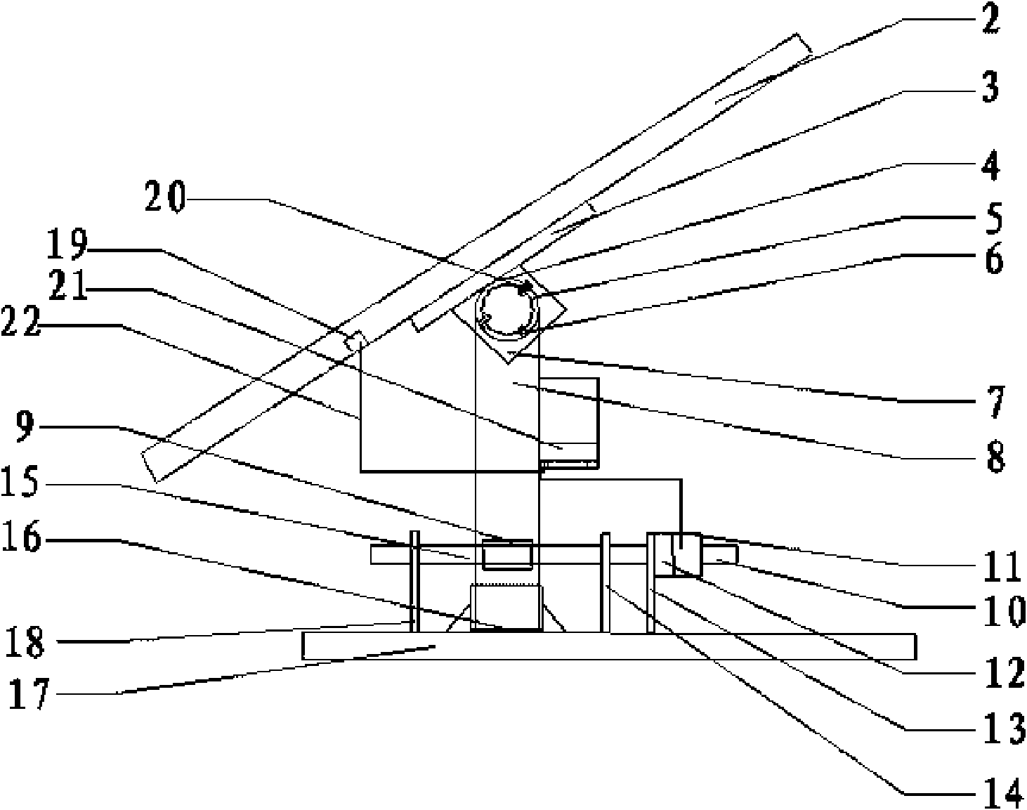
[0028] Such as Figure 5As shown, the solar tracking device includes a base 17, a main support frame 8, an azimuth actuator motor 11 with an azimuth reducer 12, an azimuth drive shaft 10, a pitch rotation shaft 5, a solar panel assembly 2, and a battery panel The component mounting frame 3 and the main controller 21, the solar cell panel assembly 2 are fixedly installed on the cell panel assembly mounting frame 3, and the cell panel assembly mounting frame 3 is fixed on the pitch angle rotating shaft 5 through the connecting plate 7, and the solar cell panel assembly 2 is vertically installed with a light sensor receiver 1, and the main controller 21 is connected with the azimuth actuator motor 11 and the light sensor receiver 1 through the control connection line 22; the pitch angle rotation shaft 5 is sleeved with a pitch angle rotation sleeve 4 , the pitch angle rotation shaft sleeve 4 circumferential surface is provided with three pitch angle adjustment holes 6, and corres...


PUM


Abstract

The invention relates to a solar tracking device, a mounting rack for a battery plate assembly is fixed on a pitching angle rotary shaft via a connecting plate, the pitching angle rotary shaft is sleeved with a pitching angle rotary shaft sleeve which is fixed on the top of a primary support rack, a pitching angle regulating hole is arranged on circumferential surface of the pitching angle rotary shaft sleeve, a corresponding bottom hole is arranged at a location corresponding to the pitching angle regulating hole on the pitching angle rotary shaft, and plug pins are plugged in the bottom hole and the pitching angle regulating hole; a support rack I and a support rack II are separately arranged at left and right sides of the primary support rack, the right side of the support rack II is provided with a support rack III, an azimuth angle actuating motor with an azimuth angle decelerator is mounted on the top of the support rack III, the front end of an azimuth angle transmission shaft is fixedly connected with worms which are mounted on the top of the support rack I and the support rack II and are cooperative with worm wheels, the worm wheels are fixedly mounted on the primary support rack, the bottom of the primary support rack is fixedly connected with a rotary bearing, and the rotary bearing, the support rack I, support rack II and the support rack III are all fixed on a base.

Description

technical field [0001] The invention relates to a solar tracking device. Background technique [0002] The current method of solar photovoltaic power generation is to let sunlight shine on a fixed flat-panel solar panel tilted at a certain angle, and the power generation efficiency is low; while the tracking-type flat-panel system is controlled by a single unit, which has a large area and uses a lot of materials; there are also panels and orientations. The execution motor system is relatively high from its installation plane, and the wind load is relatively large. It must be installed with basic engineering and construction machinery during installation, which is costly for manufacturing and installation, and the scope of application is limited, especially not suitable for use on the roof. Market promotion and the application does not work well. Contents of the invention [0003] The purpose of the present invention is to provide a new miniaturized solar tracking device s...

Claims


Application Information

Patent Timeline
Patent Type & Authority Applications(China)
IPC IPC(8): H02N6/00G05D3/12H02S20/32
CPCY02E10/50
Inventor 成佰新钱毅
Owner 江苏白兔科创新能源股份有限公司
Why Eureka
Try Eureka