Molding machine and molding method

A molding and pushing device technology, applied in the direction of molding machines, casting molding equipment, casting molds, etc., can solve problems such as defects

Inactive Publication Date: 2009-11-11
SINTOKOGIO LTD
View PDF3 Cites 2 Cited by
  • Summary
  • Abstract
  • Description
  • Claims
  • Application Information

AI Technical Summary

Problems solved by technology

Therefore a second lift may result in a defect

Method used


Image

  • Molding machine and molding method
  • Molding machine and molding method
  • Molding machine and molding method

Examples


Embodiment Construction

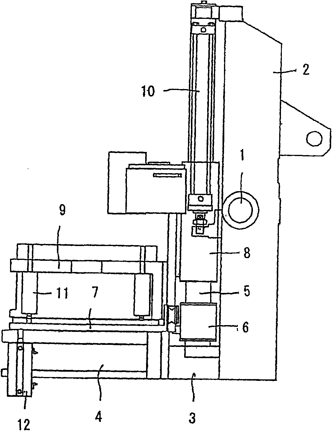
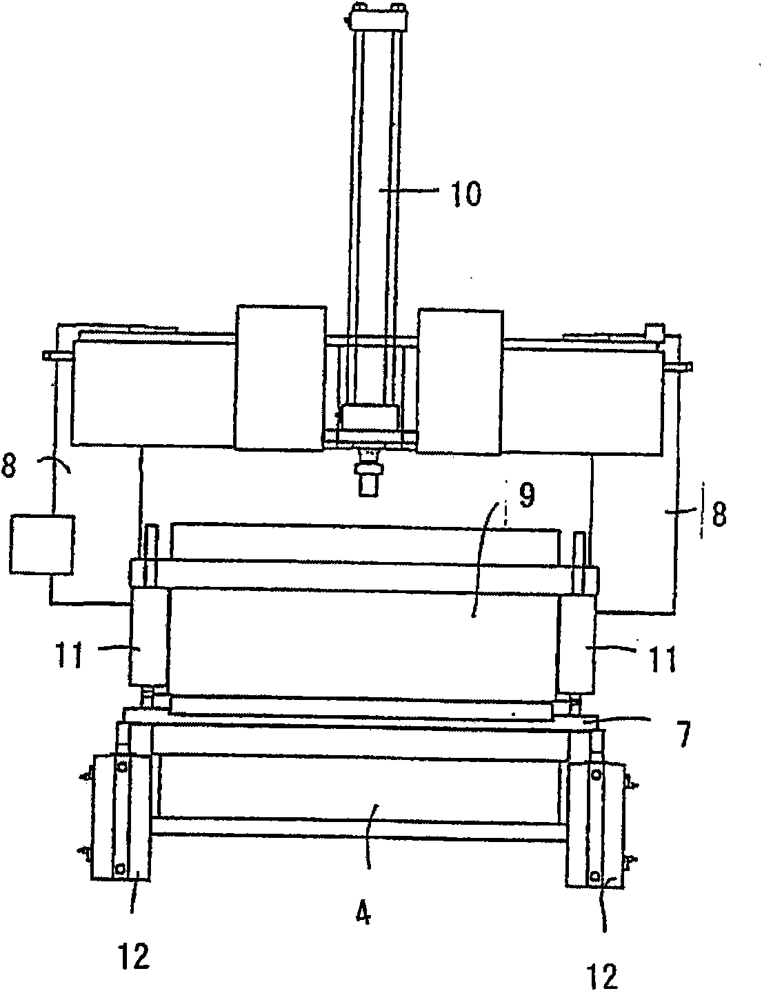
[0020] Reference below figure 1 , figure 2 and image 3 An embodiment of the double-sided template molding device of the present invention is described in detail. like figure 1 and figure 2 As shown, the styling device of the present invention comprises a rotating frame 2 extending substantially vertically. The rotating frame 2 is pivoted on a supporting shaft 1, so that the rotating frame 2 can move up and down around the supporting shaft 1 in a vertical plane. A lower flask 4 with a sand filling port on its side wall is provided at the lower end of the rotating frame 2 through a support member 3 . On the left side of the rotating frame 2, a pair of guide rods 5 extending substantially vertically are arranged back and forth at a predetermined interval. On the guide rod 5 , a double-sided template 7 is vertically arranged slidably through the guide bracket 6 . Above the guide bracket 6 adjacent to the guide rod 5 , a top flask with a sand filling port on the side wall...


PUM


Abstract

Disclosed is a molding method for separating a cope flask and a drag flask from a match plate at the same time. The method comprises the steps of: holding the match plate between the cope and drag flasks; inserting an upper squeeze member and a lower squeeze member into openings of the cope and drag flasks, which are opposed to the match plate, to define an upper molding space and a lower molding space, respectively; filling the defined molding space with molding sand; and driving the upper and lower squeeze members toward the match plate to squeeze the molding sand within the upper and lower molding space to mold an upper mold and a lower mold at the same time. The cope and drag flasks that are included within the molded upper and lower molds are forcibly pushed away from the match plate at the same time when the flasks are stationary.

Description

technical field [0001] The present invention relates to a modeling device and a modeling method, in particular to a double-sided template modeling device and a modeling method using a double-sided template. Background technique [0002] WO2005 / 058528 A1 discloses a conventional double-sided template moulding device for moulding upper and lower moulds simultaneously. In this molding apparatus, first, a double-sided template is sandwiched between an upper flask and a lower flask. Then, the upper and lower pressing members are inserted into the corresponding flasks through the openings of the flasks opposite to the double-sided template to define the upper and lower molding spaces. The molding sand is then filled into the defined molding space. Then, the upper and lower pressing members are moved to the double-sided template to squeeze the molding sand in the molding space to mold the upper and lower molds. The upper and lower flasks containing the respective upper and lower...

Claims


Application Information

Patent Timeline
Patent Type & Authority Applications(China)
IPC IPC(8): B22C11/00B22C15/08
CPCB22C11/00B22C15/08B22C9/02B22C21/02
Inventor 平田实小宫山贵之大矢英彦酒井毅坂口功一
Owner SINTOKOGIO LTD
Why Eureka
Try Eureka