Mold pump

Pending Publication Date: 2017-08-31
PYROTECK INC
View PDF11 Cites 42 Cited by
  • Summary
  • Abstract
  • Description
  • Claims
  • Application Information

AI Technical Summary

Benefits of technology

[0009]In one embodiment, a molding machine for molding material is provided. The machine includes a cavity to be filled with molten metal and a conduit system leading to the cavity, thus forming a system of interconnected hollow spaces. At least one pressure member moveable in at lea

Problems solved by technology

Unfortunately, the delivery and balance tubes of these apparatus can degrade over time and/or leak, resulting in poor shot size control.
However, such devices are complicated, expensive to manufacture and can be difficult to operate.
The system of FIG. 1 suffers from drawbacks including variations in efficiency resulting from degradation of the gas introduction components, the fact that a closed system is hard to refill, the fact that compressibility of gas degrades precision, and the requirement that a significant amount of space is consumed.
Although centrifugal pumps ope

Method used


Image

  • Mold pump
  • Mold pump
  • Mold pump

Examples


Embodiment Construction

[0023]It is to be understood that the detailed figures are for purposes of illustrating the exemplary embodiments only and are not intended to be limiting. Additionally, it will be appreciated that the drawings are not to scale and that portions of certain elements may be exaggerated for the purpose of clarity and ease of illustration.

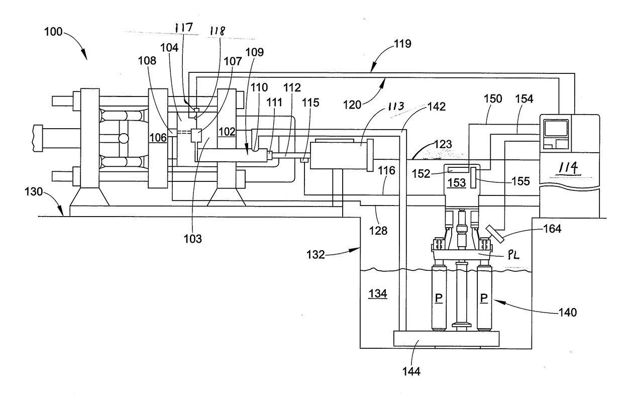
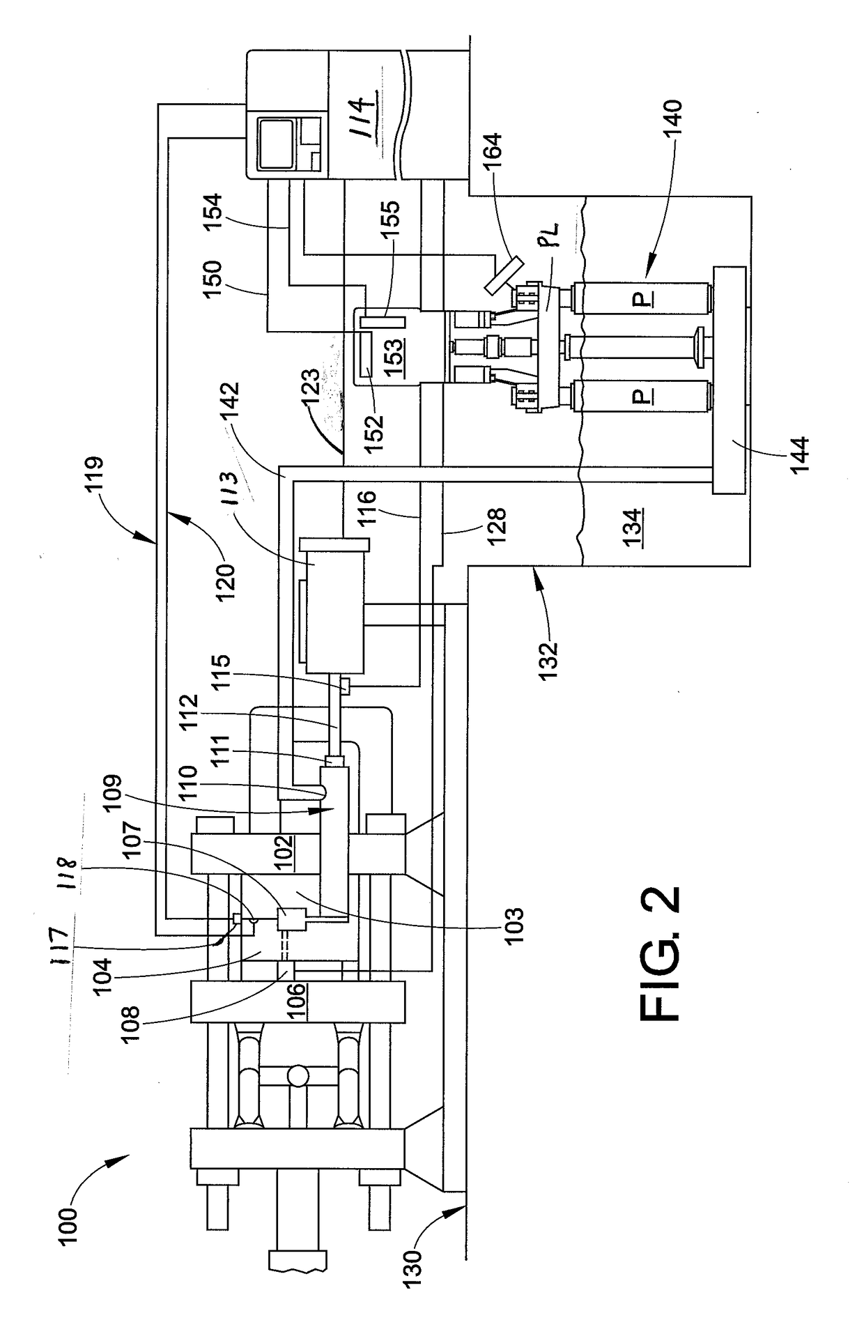
[0024]The use of a centrifugal molten metal pump in the process of die casting is highly challenging. A typical die casting cycle time is 30 to 90 seconds, which requires a shot sleeve to be filled in approximately 3 to 10 seconds. Furthermore, the delivered quantity of molten metal should be within about 2% of the expected quantity. Similarly, it is desirable to provide an initial “slow” speed fill period (e.g. ¼ cycle time), an intermediate “high” speed fill period (e.g. ½ cycle time), and a third pressurized hold period (e.g. ¼ cycle time). The present disclosure is directed to a system that can fulfill these requirements.

[0025]With reference to FIG...


PUM

PropertyMeasurementUnit
Weightaaaaaaaaaa
Pressureaaaaaaaaaa
Lengthaaaaaaaaaa

Abstract

A molding machine for molding material is provided. The machine includes a cavity to be filled with molten metal and a conduit system leading to the cavity, thus forming a system of interconnected hollow spaces. At least one pressure member is moveable in at least part of the conduit system. A centrifugal pump in fluid communication with a reservoir of molten metal is provided, the pump providing molten metal to the hollow space receiving the at least one pressure member.

Description

BACKGROUND[0001]The present exemplary embodiment relates to a process and apparatus for delivering a measured shot of molten metal. It finds particular application in conjunction with a shot sleeve of a die-casting machine and will be described with particular reference thereto. However, it is to be appreciated that the present exemplary embodiment is also amenable to other similar applications including delivery of a measured shot to a pour cup, ladle, or mold.[0002]In die casting of ferrous and non-ferrous (e.g. aluminum) products, metal is melted in a furnace. The molten metal is stored in a molten state ready for delivery to a mold. A metered amount of molten metal is delivered to the mold. Several devices have been proposed which will deliver a metered amount of molten metal or a shot to the mold. For example, ladeling, magnetic pumps and pressurized furnaces have been employed.[0003]One example of a pressurized furnace is described in U.S. Pat. No. 2,846,740 (the disclosure of...

Claims


Application Information

Patent Timeline
IPC IPC(8): B22D39/04B22D13/10B22D13/12B22D35/04B22D17/20B22D17/30B22D17/32B22D13/02B22D17/08
CPCB22D39/04B22D13/02B22D13/107B22D13/12B22D35/04B22D17/2023B22D17/203B22D17/30B22D17/32B22D17/08F04D7/065F04D15/0066
Inventor TIPTON, JONHORSFALL, ANDREWFRITZKE, JAYHENDERSON, RICHARD S.
Owner PYROTECK INC
Why Eureka
Try Eureka