Injection machine having a lubrication mechanism and a lubrication method of an injection machine

a technology of injection molding machine and lubrication mechanism, which is applied in the direction of gearing details, food shaping, and parts of the ball screw that cannot can solve the problems of uneven lubrication condition of the entire ball screw, low fluidity, and inability to maintain a lubrication film, etc., to suppress the temperature rise of the conversion mechanism and the effect of sufficient lubrication

Inactive Publication Date: 2005-11-17
SUMITOMO HEAVY IND LTD
View PDF6 Cites 45 Cited by
  • Summary
  • Abstract
  • Description
  • Claims
  • Application Information

AI Technical Summary

Benefits of technology

[0014] According to the above-mentioned invention, the lubrication material of a liquid state is directly sprayed in the vicinity of a part, which needs lubrication, since the lubrication material is atomized and sprayed over the component part of the conversion mechanism. Accordingly, sufficient lubrication is achieved even if the lubrication material is in a liquid state. Additionally, heat generated by the conversion mechanism is caused to be absorbed by the lubricant material in a liquid state so as to suppress a temperature rise of the conversion mechanism.
[0015] In the above-mentioned invention, it is preferable to further comprise a recovery route adapted to recover the lubrication material sprayed from the spray nozzle, wherein the spray nozzle is a nozzle that atomizes the lubrication material of a liquid state by an injection of a gas. Since the atomized lubrication material changes into a liquid state by being brought into contact with the component part, the lubricant material in the liquid state can be recovered and reused. Further, since the liquid state lubrication material, which has absorbed heat of the component part of the conversion mechanism, is recovered, the temperature rise of the conversion mechanism can be suppressed.

Problems solved by technology

However, since grease has a low fluidity and a high viscosity, the grease supplied to a part of the ball screw cannot maintain a lubrication film uniformly in its entirety, and a lubricating condition of the entire ball screw may become uneven.
However, according to such a method, an amount of consumption of the grease, which is relatively expensive, is increased, which results in an increase in a maintenance cost of the injection molding machine.
Additionally, if the amount of grease is increased, excessive grease scatters in and around the molding machine, which creates an extremely bad environment due to pollution of in surrounding area of the molding machine.
Moreover, since the ball screw operates frequently during an operation of the molding machine and a large load is applied to the contact portions of the balls, a frictional heat is generated at the contact portions of the balls.
Thereby, the ball screw becomes a high temperature, which is a factor of reducing the service life of the ball screw.
However, the above-mentioned grease provides only a lubricating action by staying at the heat-generating portion, and a heat-releasing effect or a cooling effect cannot be expected.

Method used


Image

  • Injection machine having a lubrication mechanism and a lubrication method of an injection machine
  • Injection machine having a lubrication mechanism and a lubrication method of an injection machine
  • Injection machine having a lubrication mechanism and a lubrication method of an injection machine

Examples


Embodiment Construction

[0031] A description will be given, with reference to the drawings, of a mode for carrying out the present invention.

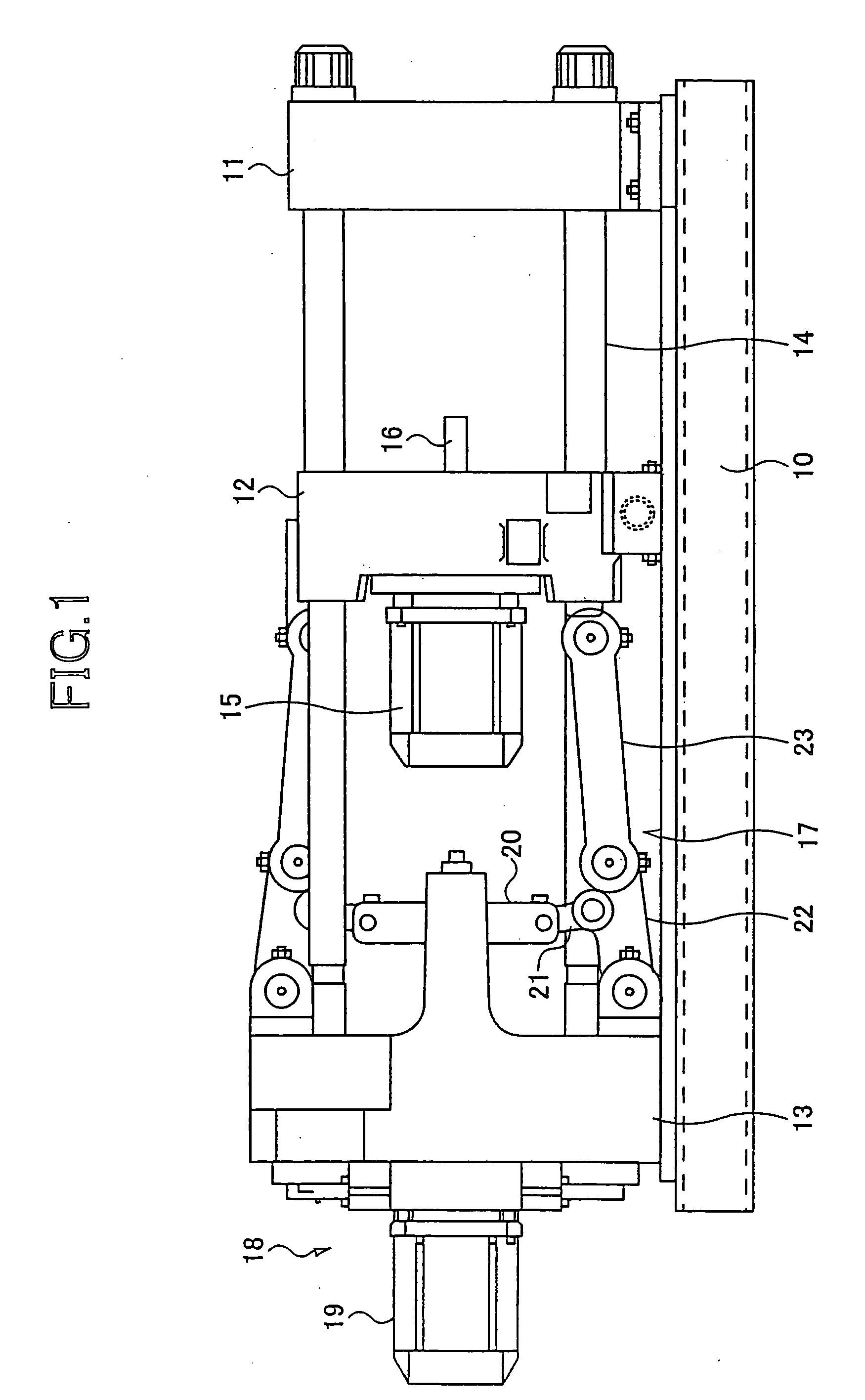
[0032] First, a description will be given of an example of a clamping apparatus of an injection molding machine into which a lubrication mechanism according to the present invention is incorporated. FIG. 1 is an outline structure diagram of the example of the clamping apparatus in which the lubrication mechanism according to the present invention is incorporated.

[0033] The clamping apparatus shown in FIG. 1 comprises a stationary platen 11 fixed to a frame 10 and a movable platen 12 movable relative to the stationary platen. A toggle support 13 as a base support is movably provided relative to the frame 10 with a predetermined distance to the stationary platen 11. Tie bars 14 are provided between the fixed platen 11 and the toggle support 13. The movable platen 12 is arranged in a state where it faces the stationary platen 11, and is movable along the tie bars 14.

[...


PUM

PropertyMeasurementUnit
moving speedaaaaaaaaaa
fluidityaaaaaaaaaa
viscosityaaaaaaaaaa

Abstract

A molding machine having a lubrication mechanism according to the present invention can effectively rubricate a ball screw and elongate a service life of the ball screw. In a clamping apparatus of an electric injection molding machine, a rotational movement of a rotational shaft of a motor is converted into a linear movement in an axial direction by a ball screw mechanism. Atomized lubrication oil is directly sprayed inside the ball screw nut from a spray nozzle. The lubrication oil, which has been sprayed from the spray nozzle, is recovered and reused.

Description

CROSS REFERENCE TO RELATED APPLICATIONS [0001] This application is a U.S. continuation application filed under 35 U.S.C. 111(a) claiming benefit under 35 U.S.C. 120 and 365(c) of PCT application JP2004 / 000578, filed Jan. 23, 2004, which claims priority to Application Ser. No. 2003-017556, filed in Japan on Jan. 27, 2003. The foregoing applications are hereby incorporated herein by reference.BACKGROUND OF THE INVENTION [0002] 1. Field of the Invention [0003] The present invention relates to injection molding machines and, more particularly, to an electric injection molding machine having a lubrication mechanism and a lubricating method thereof. [0004] 2. Description of the Related Art [0005] Generally, an injection molding machine, which performs resin molding, molds a resin component by filling a resin, which has been heated and melted in a heating cylinder, into a cavity of a mold, and cooling and solidifying the resin. Generally, a mold for resin-molding consists of a stationary m...

Claims


Application Information

Patent Timeline
Patent Type & Authority Applications(United States)
IPC IPC(8): B29C45/50B29C45/83F16H25/22F16H25/24F16H57/04
CPCB29C45/5008B29C45/83B29C2045/835Y10T74/18744F16H25/24F16H57/0456F16H57/0497F16H25/2214
Inventor HIRAGA, HORITSUGU
Owner SUMITOMO HEAVY IND LTD
Why Eureka
Try Eureka