Platen

a plate and plate body technology, applied in the field of plate body, can solve the problems of affecting the quality of plate body, and affecting the quality of plate body, and achieve the effect of efficient coupleing of forces

Active Publication Date: 2006-07-25
HUSKY INJECTION MOLDING SYST LTD
View PDF37 Cites 43 Cited by
  • Summary
  • Abstract
  • Description
  • Claims
  • Application Information

AI Technical Summary

Benefits of technology

[0023]The ribs are preferably associated with gussets which extend from the rib to the intermediate support structure. Preferably, the gusset and associated rib are integrally formed. T...

Problems solved by technology

Approaching the issue of flatness (or, in fact, the lack of flatness) between platens and the mold halves from a reverse perspective, mold halves that are fractionally misaligned through bowing of their contact faces can suffer from part formation problems, usually related to mold “flash”.
When a mold and platen arrangement is closed and clamped-up in a first phase of the molding operation an equilibrium is reached but the injection of plastics material into the mold halves can cause a separation line to open up because of a lack of uniform back-up for the mold.
This causes mold flash to be formed.
There are several undesirable effects pertaining to the formation of flash in a molding process.
Assuming that a resultant part is usable, an additional processing technique must be employed to remove the flash; this adds to time and cost in producing a product.
Also, the removal process itself may not be entirely successful and some flash may therefore remain to spoil the finish of the article.
Alternatively, flash may simply render the finished article unusable either as a consequence of the part being physically deformed or significantly u...

Method used


Image

  • Platen
  • Platen
  • Platen

Examples


Embodiment Construction

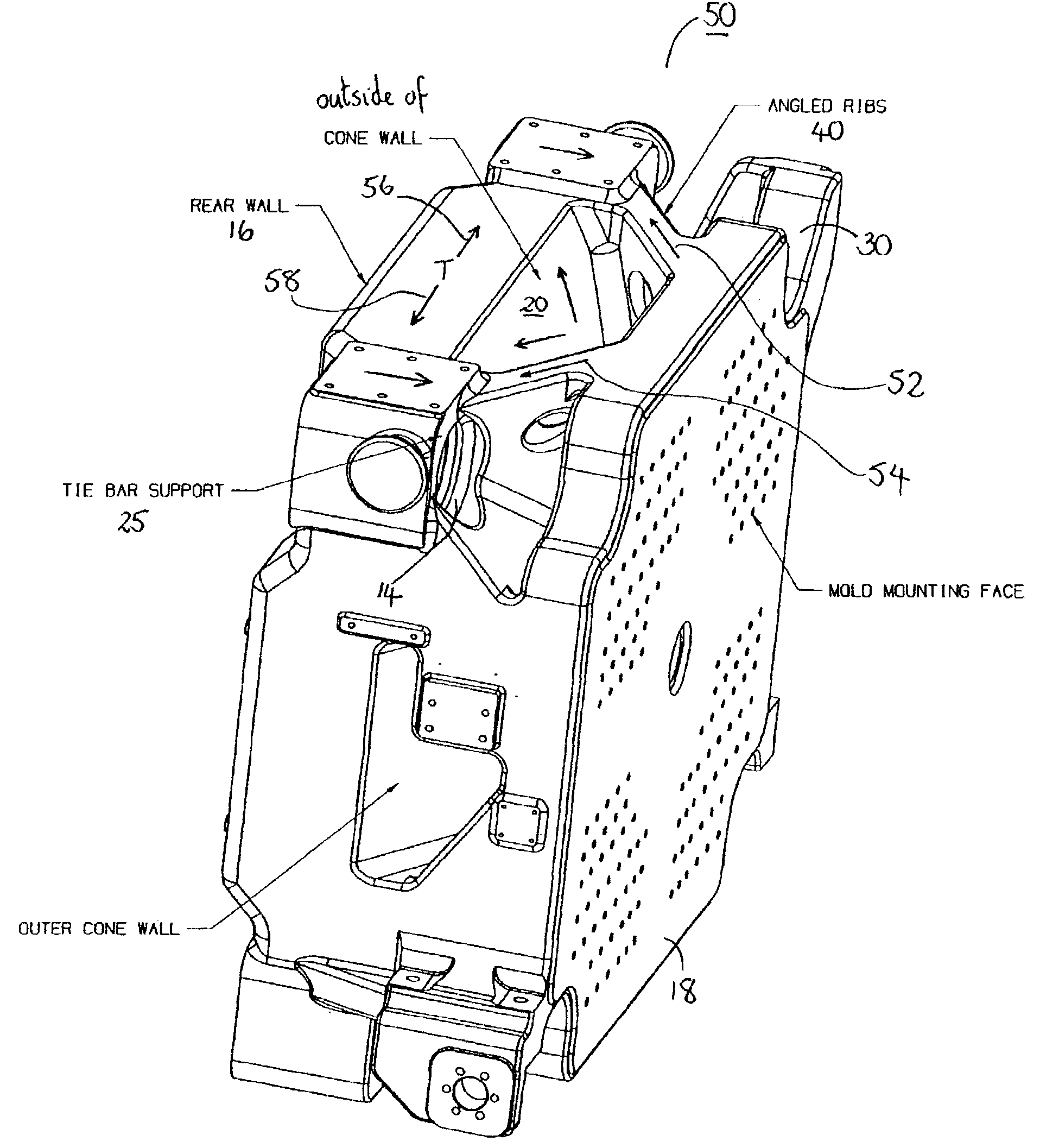
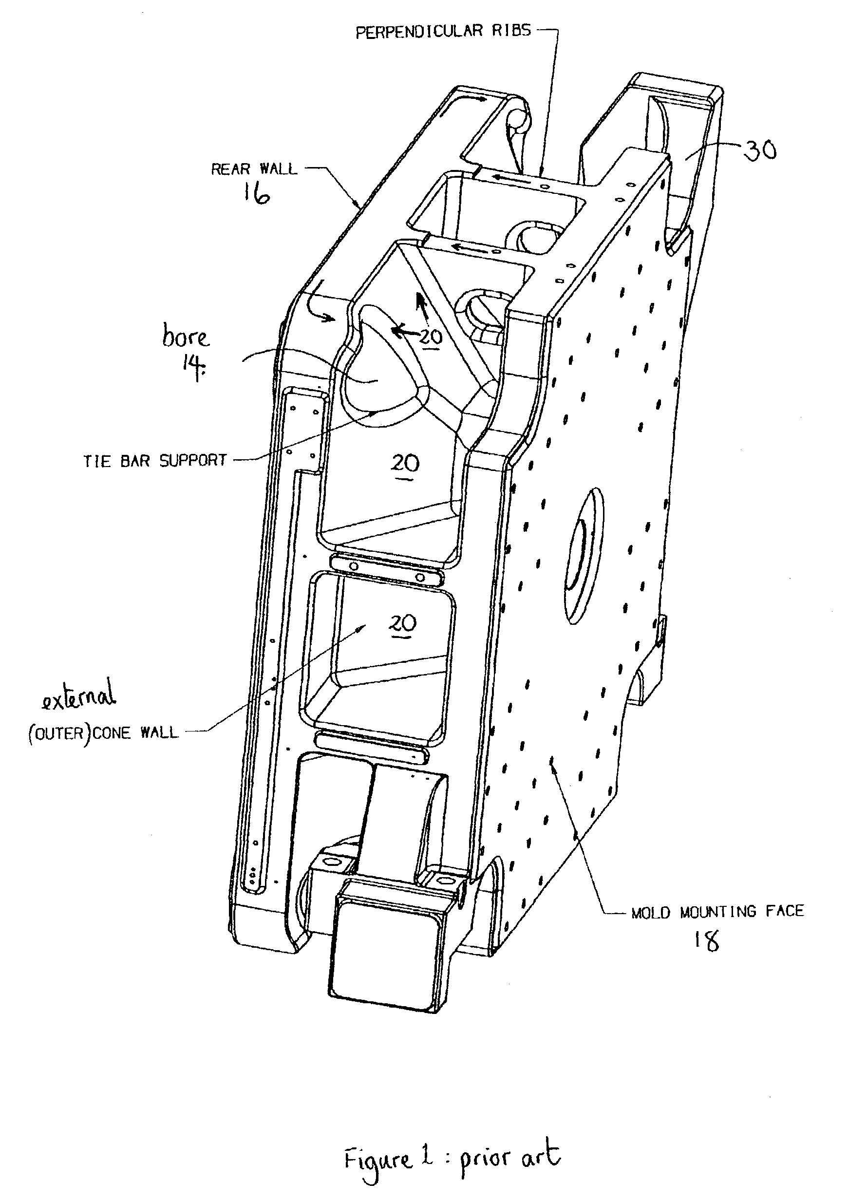
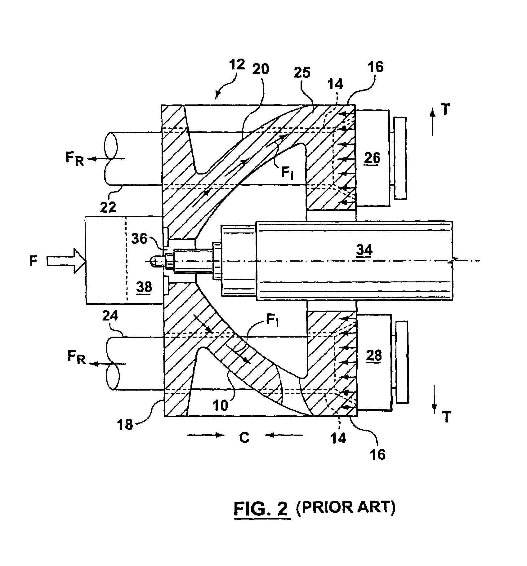
[0034]Referring to the drawings in greater detail, FIG. 2 is a sectional view of a REFLEX® platen 10 shown in the context of a schematic partial representation of an injection molding machine 12. The REFLEX® platen 12 is provided with bores 14 (shown in broken outline) located at the four corners of the rear face 16. A front wall / face 18 of the REFLEX® platen 12 is coupled to the rear wall through an intermediate support structure 20, typically on a generally conical or cone-like construction as taught in U.S. Pat. No. 5,593,711. This intermediate support structure extends substantially from the outer edges of the rear wall 13 towards an inner central portion of the front wall 12, with the intermediate support structure 20 skirting or including the bore 14 for the tie-bars.

[0035]Tie bar pairs 22 and 24 are coupled (or selectively coupled depending on whether the platen is a stationary platen or a moving platen) to the rear wall 16 by tie-bar nuts 26 and 28. The tie-bar nuts can be s...


PUM

PropertyMeasurementUnit
Angleaaaaaaaaaa
Angleaaaaaaaaaa
Angleaaaaaaaaaa

Abstract

A platen (50) for a molding machine includes an intermediate support structure (20) between two planar walls (16, 18) having ribs (40) arranged at a non-normal angle β to a first wall (18). The ribs (40) couple forces from the first wall (18) to the second wall (16) in such a way that bending of the second wall (16) is resisted. This adds to the rigidity of the second wall (16) and hence the platen (50), adding to flatness of the arrangement. Gussets (42) may be provided extending between the ribs (40) and the intermediate support structure (20). This has the effect of surrounding and supporting an injection bore (14) and further adding to the coupling of forces to the edge portions of the second wall (16) to resist forces acting to bend the wall.

Description

BACKGROUND OF INVENTION[0001]1. Field of the Invention[0002]This invention relates to a platen for use in industrial machines, particularly presses such as injection molding machines, and particularly, but not exclusively, plastic injection-molding machines operating with a large clamp force / closure tonnage.[0003]2. Background Information[0004]Platens are essentially robustly constructed support structures that locate, support and align mold halves under applied clamp / closure tonnage. Each platen in a system must therefore be arranged to convey force effectively to the mold. In a molding process, as will be understood, it is important to maintain a high degree of parallelism between surfaces of a platen (and also between platens), since distortion in the platen correspondingly and usually induces distortion in a mold half (and particularly the mold face) located within the platen. Indeed, under applied clamp tonnage, platens should ideally be entirely resilient to physical distortio...

Claims


Application Information

Patent Timeline
IPC IPC(8): B29C45/17
CPCB29C45/1744B29C45/17F16S1/10B29C45/64
Inventor GLAESENER, PIERRE
Owner HUSKY INJECTION MOLDING SYST LTD
Why Eureka
Try Eureka