
Gas gathering system of divisional gas-gathering type aluminum electrolytic bath

An aluminum electrolytic cell and electrolytic cell technology, which is applied in the field of gas collection system, can solve the problems of the V-shaped structure device being close to the fire hole, the limitation of gas collection efficiency, and the complicated upper structure, so as to improve the uniformity of negative pressure distribution in the tank and reduce the Weight, effect of improving tank life

Inactive Publication Date: 2009-11-18
NORTHEASTERN UNIV ENG & RES INST CO LTD
View PDF0 Cites 3 Cited by
  • Summary
  • Abstract
  • Description
  • Claims
  • Application Information

AI Technical Summary

Problems solved by technology

Although this structure has achieved a relatively obvious gas collection effect, it still fails to solve the problem that the original V-shaped structure device is too close to the fire hole, and the gas collection efficiency is still limited.
[0004] The structural forms of the above-mentioned several gas-collecting devices, no matter how they are adjusted, there is a problem, that is, the gas-collecting device is located above the tank and occupies the upper space. In this way, on the one hand, the upper structure becomes complicated; Gas efficiency, the height of the tank will be forced to increase, which will not only increase equipment investment but also increase the height of the plant

Method used


Image

  • Gas gathering system of divisional gas-gathering type aluminum electrolytic bath
  • Gas gathering system of divisional gas-gathering type aluminum electrolytic bath
  • Gas gathering system of divisional gas-gathering type aluminum electrolytic bath

Examples


Embodiment 1

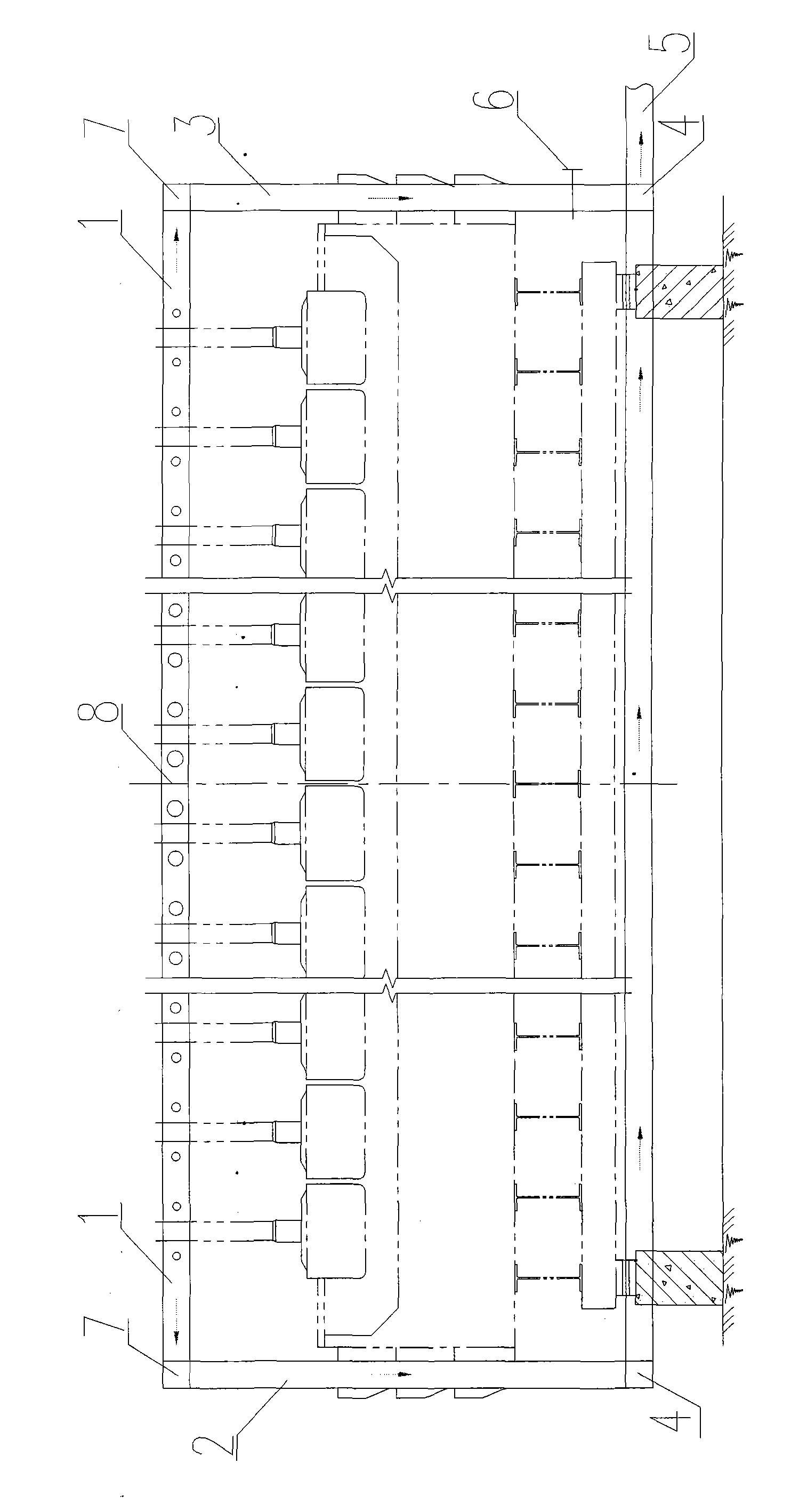
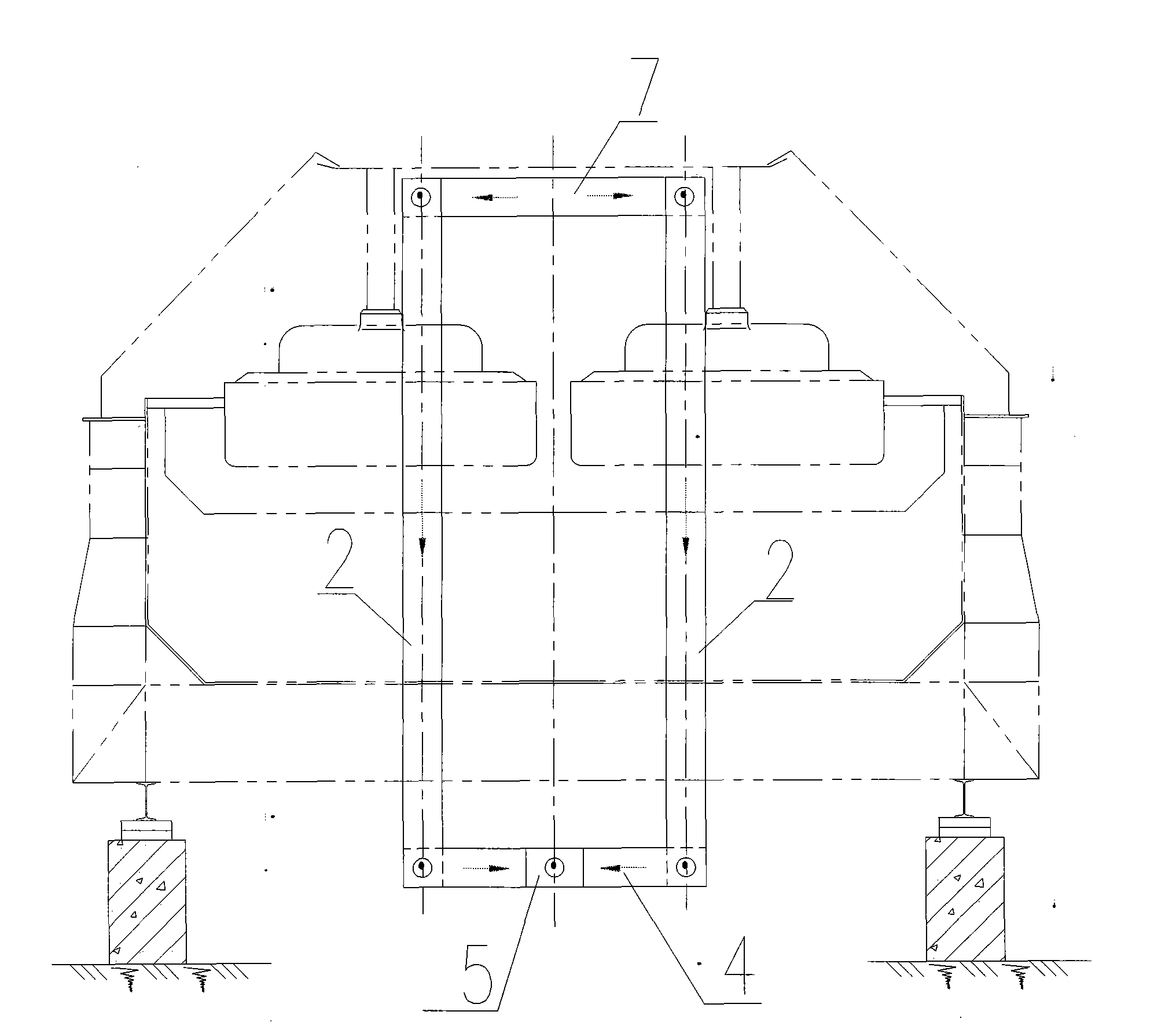
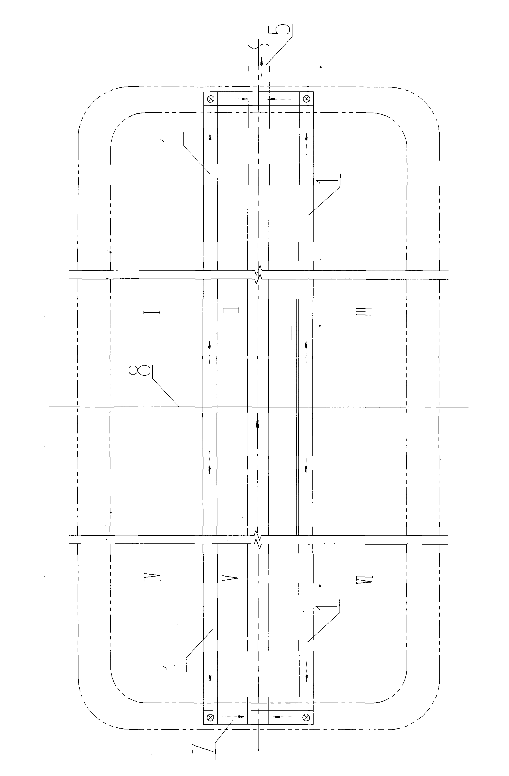
[0030] Such as figure 1 , figure 2 , image 3 As shown, it is the structural form of the gas collection system ① of the partitioned gas collection type aluminum electrolytic cell of the present invention. The gas collection system includes a horizontal flue 1 in the tank, a partition 8, a vertical flue 2 on the left, and a vertical flue 3 on the right. , Bottom confluence flue 4, upper confluence flue 7, total flue 5 and regulating valve 6. The horizontal cover plates on the upper part of the horizontal flue in the groove are combined together, the number is 2, and the height of the horizontal flue in the groove is 300mm. The baffle is perpendicular to the length direction of the horizontal flue and divides its length equally. In this way, the horizontal flue and the baffle divide the horizontal gas-gathering area into 6 areas I, II, III, IV, V, and VI. The upper converging flue 7 is arranged at both ends of the horizontal flue in the tank and communicates with both ends o...

Embodiment 2

[0033] Such as Figure 4 As shown, it is the structural form of the gas collection system of the partitioned gas collection type aluminum electrolytic cell of the present invention ②, the gas collection system includes a horizontal flue 1 in the tank, a partition 8, a vertical flue 2 on the left, and a vertical flue 3 on the right , the bottom confluence flue 4, the upper confluence flue 7, the total flue 5 and the regulating valve 6. The horizontal flue in the tank is independent, the number is 5, and the height of the horizontal flue in the tank is 400mm. The baffle is perpendicular to the length direction of the horizontal flue and equally divides its length. In this way, the horizontal flue and the baffle divide the horizontal gas-gathering area into multiple areas, and the number of areas is 12. The upper converging flue 7 is arranged at both ends of the horizontal flue 1 in the tank, and communicates with both ends of the horizontal flue 1 in the tank. The left vertica...

Embodiment 3

[0036] Such as Figure 5 As shown, it is the structural form of the gas collection system of the partitioned gas collection type aluminum electrolytic cell of the present invention ③, the gas collection system includes a horizontal flue 1 in the tank, a partition 8, a vertical flue 2 on the left, and a vertical flue 3 on the right , Bottom confluence flue 4, upper confluence flue 7, total flue 5. The horizontal flue 1 in the groove is combined with the horizontal cover plate on the upper part of the groove, the number is 3, and the height of the horizontal flue 1 in the groove is 100mm. The baffle is perpendicular to the length direction of the horizontal flue and divides its length equally. In this way, the horizontal flue and the baffle divide the horizontal gas-gathering area into multiple areas, and the number of areas is 8. The upper converging flue 7 is arranged at both ends of the horizontal flue in the tank and communicates with both ends of the horizontal flue in the...


PUM

PropertyMeasurementUnit
heightaaaaaaaaaa
heightaaaaaaaaaa
heightaaaaaaaaaa

Abstract

The invention relates to a gas gathering system of a divisional gas-gathering type aluminum electrolytic bath, which belongs to the technical field of electrolyzing aluminum. The gas gathering system of the electrolytic bath comprises in-bath horizontal flues, clapboards, vertical flues, upper convergence flues, bottom convergence flues and a main flue, wherein the number of the in-bath horizontal flues is between 2 and 5, the height range is between 100 and 400 millimeters; the clapboards are vertical to the length direction of the horizontal flues and equally divide the length of the horizontal flues; and the horizontal flues and the clapboards divide a horizontal gas-gathering area into a plurality of areas. The vertical flues are arranged at one end or two ends of the electrolytic bath, have a same structure with a door-type upright post or are positioned on the outside of the door-type upright column, and are communicated with the main flue though the bottom convergence flues. By applying the system, a two-end or single-end gas-gathering mode can be adopted, and no matter which gas-gathering mode is adopted, a plurality of the in-bath horizontal flues are arranged to divide the in-bath space into a plurality of areas to perform divisional gas gathering, and the distribution evenness of positive pressure in the bath is improved, thus the gas gathering efficiency is improved.

Description

technical field [0001] The invention belongs to the technical field of electrolytic aluminum, and in particular relates to a gas collection system of a partitioned gas collection type aluminum electrolytic cell. Background technique [0002] As the capacity of the aluminum electrolytic cell increases, the length of the electrolytic cell increases accordingly. In this case, the structural form of the gas collecting device on the upper part of the tank with the traditional structure can no longer meet the requirements of the pressure distribution in the electrolytic cell cover, especially in the environment of energy saving and emission reduction, the structural form of the gas collecting device has a great impact on the electrolytic aluminum industry. The role of emission reduction becomes even more important. [0003] The early large-scale prebaked anode electrolyzer mostly used a V-shaped structure gas collector under the horizontal cover plate. In this gas collection met...

Claims


Application Information

Patent Timeline
Patent Type & Authority Applications(China)
IPC IPC(8): C25C3/22
Inventor 马成贵戚喜全班允刚毛宇裴泽慧毛继红董慧
Owner NORTHEASTERN UNIV ENG & RES INST CO LTD
Learn More