Electric filter dimming device control circuit

A technology of dimming device and control circuit, applied in non-electric variable control, light control, filter and other directions, can solve the problem of large changes in incident light intensity and spectrum, and achieve the effect of easy expansion and upgrade

Inactive Publication Date: 2011-04-20
INST OF OPTICS & ELECTRONICS - CHINESE ACAD OF SCI
View PDF1 Cites 0 Cited by
  • Summary
  • Abstract
  • Description
  • Claims
  • Application Information

AI Technical Summary

Problems solved by technology

An existing mobile filter control method and system application number is 200810065623.1, which can execute commands to open and close the mobile filter or automatically switch the working state of the mobile filter, but can only open or close the filter. Can't switch between filters in different gears
However, due to changes in the application scenarios of optical instruments and the external environment, such as: different seasons and weather, the high angle of the sun and the characteristics of the scene, and the changes between night and day, the intensity and spectrum of the incident light vary greatly. In order to obtain a clear image on the CCD , under different environmental backgrounds, it is necessary to quickly and accurately control the filter dimming device, and perform shift dimming between filters with different transmittances

Method used


Image

  • Electric filter dimming device control circuit
  • Electric filter dimming device control circuit
  • Electric filter dimming device control circuit

Examples


Embodiment Construction

[0017] In order to make the object, technical solution and advantages of the present invention clearer, the present invention will be further described below in conjunction with the accompanying drawings and embodiments. It should be understood that the specific embodiments described here are only used to explain the present invention, but not to limit the present invention.

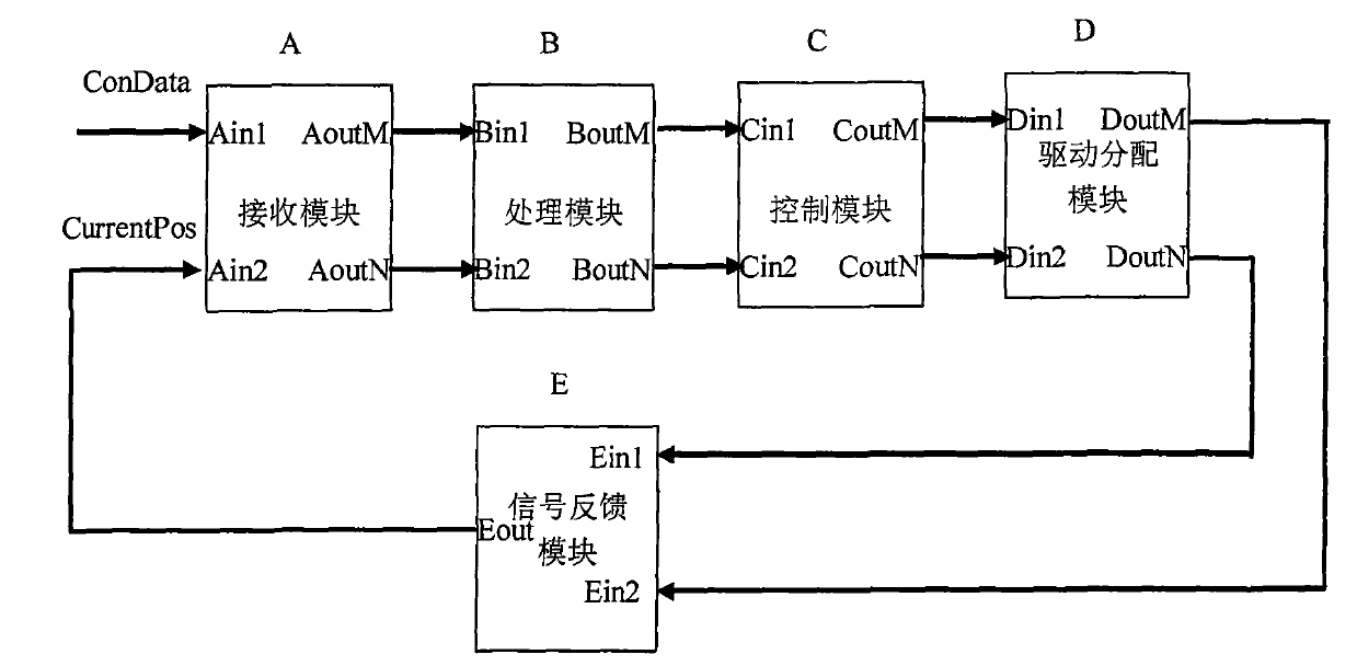
[0018] Such as figure 2 As shown, the electric filter dimming control circuit of the present invention includes: a signal receiving module A, a signal processing module B, a control module C, a drive distribution module D, and a signal feedback module E. The control command ConData input by the user includes the serial number Number of a certain dimming device to be adjusted by the user and the gear position signal IdealPos to be reached by the filter. Among them, the serial number of the dimming device Number and the gear position signal IdealPos are natural numbers, Number∈M, M is the serial number o...


PUM


Abstract

An electric filter dimming device control circuit completes accuracy control of the electric filter dimming device by signal processing and logic control in a programmable logic device, the method comprises the following modules: a signal receiving module A, a signal processing module B, a control module C, a drive distribution module D and a signal feedback module E. The invention solves the problem of automatic control of the dimming devices of photoelectric instruments and flexibly realizes gear switching of the electric filter dimming device; the invention further has stable working performance, is easy to expand and upgrade and satisfies the automation requirements of modern optical instruments.

Description

technical field [0001] The invention belongs to the field of optical instruments and photoelectric imaging, and in particular relates to a control circuit of an electric filter mirror dimming device. Background technique [0002] The motorized filter dimming device is a dimming device widely used in the fields of optical instruments and photoelectric imaging, which can correct the incoming light of a charge-coupled image sensor (CCD). Adding a filter dimming device to the optical system can improve the contrast between the object and the background, thereby obtaining better image clarity. A general electric filter dimming device is mainly composed of a dimming motor, a worm rolling bearing, a worm wheel, a position diode, a filter, a code disc, etc., such as the application number of an existing three-line coding dimming device: 200810239212.7C. figure 1 It is a schematic diagram of the coding disc of the electric filter dimming device, wherein, gear group number 1 to gear ...

Claims


Application Information

Patent Timeline
Patent Type & Authority Patents(China)
IPC IPC(8): G05D25/02G02B5/20
Inventor 王彩霞黄奎李恩德李梅任绍恒王春鸿周璐春周睿
Owner INST OF OPTICS & ELECTRONICS - CHINESE ACAD OF SCI
Why Eureka
Try Eureka