
Camera array calibration algorithm based on gray level image and spatial depth data

A technology of spatial depth and grayscale images, applied in the field of calibration algorithms including arrays of 3D cameras, can solve problems such as low resolution, large errors, and influence of calibration accuracy, and achieve high precision and simple effect.

Inactive Publication Date: 2009-11-18
ZHEJIANG UNIV
View PDF0 Cites 42 Cited by
  • Summary
  • Abstract
  • Description
  • Claims
  • Application Information

AI Technical Summary

Problems solved by technology

Traditional calibration algorithms are relatively mature on ordinary cameras. However, for 3D cameras, due to their low resolution and different imaging methods, the calibration accuracy of traditional calibration algorithms has been greatly affected, especially in the calculation of external parameters. In terms of links, the error is relatively large

Method used


Image

  • Camera array calibration algorithm based on gray level image and spatial depth data
  • Camera array calibration algorithm based on gray level image and spatial depth data
  • Camera array calibration algorithm based on gray level image and spatial depth data

Examples


Embodiment Construction

[0015] Below, the present invention will be further described in conjunction with the accompanying drawings and specific embodiments.

[0016] The visible light camera used in this embodiment uses a CCD sensor, which can provide a color image or a grayscale image with a resolution of 768×576. The 3D camera used is a Swiss Ranger 3000 (TOF camera), which can provide a resolution of 176× 144 depth and grayscale images.

[0017] When shooting the calibration plate image, in order to increase the robustness of corner detection and the stability of the image data, multiple frames of images can be taken continuously for the calibration plate at the same position, and then the average value is calculated as the actual value we use in calibration. image.

[0018] In the process of internal calibration of each camera, the selected tool is the calibration toolkit ToolBox_Calib provided by Matlab. The internal algorithm of the toolkit is based on the two-step calibration method of Zhang...


PUM


Abstract

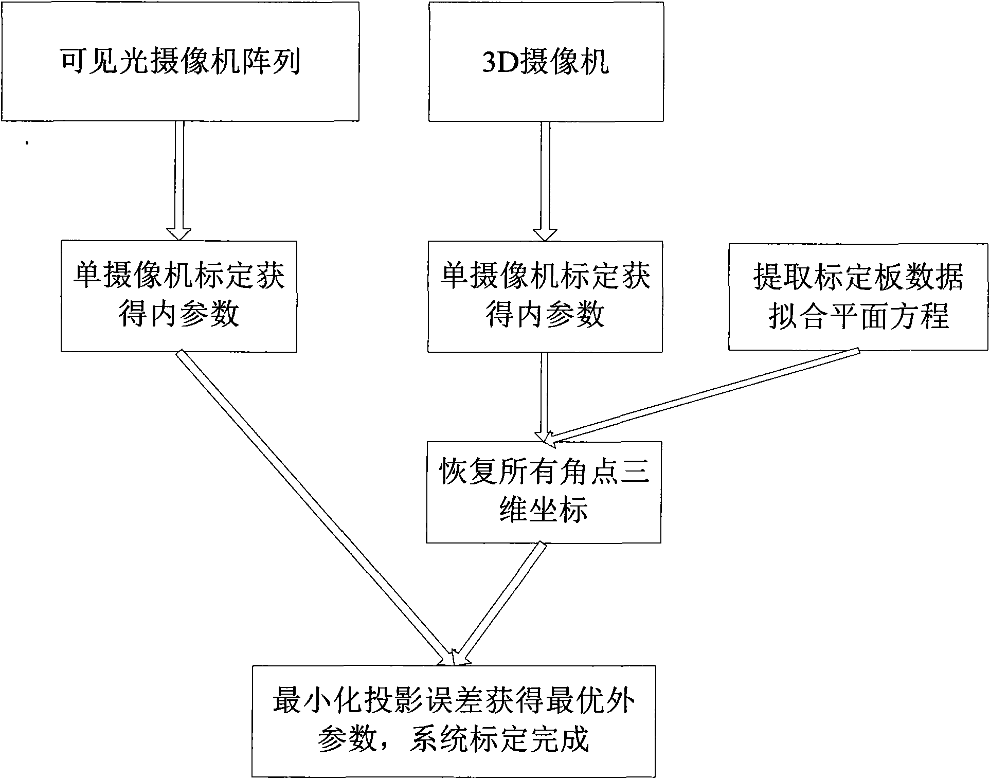
The invention provides a camera array calibration algorithm capable of calibrating a 3D camera and obtaining relatively precise extrinsic parameters between the 3D camera and a visible light camera. The algorithm comprises the following steps: firstly, internally calibrating the visible light camera and the 3D camera to obtain intrinsic parameters of the cameras; secondly, adopting the intrinsic parameters of and a depth map provided by the 3D camera to restore the spatial locations of corner points of calibration boards, adopting minimum corner point projection error to obtain the optimum extrinsic parameters from the 3D camera to the required visible light camera, thereby completing the calibration of the whole camera array.

Description

technical field [0001] The invention relates to a camera calibration algorithm, in particular to a calibration algorithm including an array of 3D cameras based on grayscale images and depth data. Background technique [0002] In recent years, obtaining the actual distance from the object to the sensor has become a very popular topic in the field of computer vision research. Scholars at home and abroad have done a lot of work and proposed many related methods. However, so far, there are always many unsolvable problems in traditional algorithms, such as defects in calculation accuracy and real-time performance. [0003] With the development of new sensor technologies, it becomes possible to obtain real-time depth information of dynamic scenes, such as Time-of-Flight. This new sensor technology adopts new infrared detection technology, emits infrared light to each point on the sensor, and calculates the distance between each point in the scene and the sensor by detecting the t...

Claims


Application Information

Patent Timeline
IPC IPC(8): G06T7/00
Inventor 于慧敏周颖吴嘉
Owner ZHEJIANG UNIV
Learn More