Illuminating device, and input device having the former

A technology for lighting devices and input devices, which is applied to lighting devices, illuminated signs, lighting and heating equipment, etc., can solve the problems of large difference in illuminance and the surface of the surface of the light guide layer is not uniformly illuminated, etc., to prevent Effects of light loss, simple structure, and easy thinning

Inactive Publication Date: 2009-11-18
ALPS ALPINE CO LTD
View PDF1 Cites 15 Cited by
  • Summary
  • Abstract
  • Description
  • Claims
  • Application Information

AI Technical Summary

Problems solved by technology

[0007] In addition, there is a problem in the conventional lighting device that it is bright near the light source, but the ratio of getting darker as it moves away from the light source is large, and the illuminance difference is large.
[0008] In addition, there is a problem in the conventional illuminating device that due to scattering of stray light, relatively bright parts (spots) are formed in an island shape on the surface of the light guide layer, and the surface of the surface of the light guide layer is not uniformly illuminated.

Method used


Image

  • Illuminating device, and input device having the former
  • Illuminating device, and input device having the former
  • Illuminating device, and input device having the former

Examples


Embodiment Construction

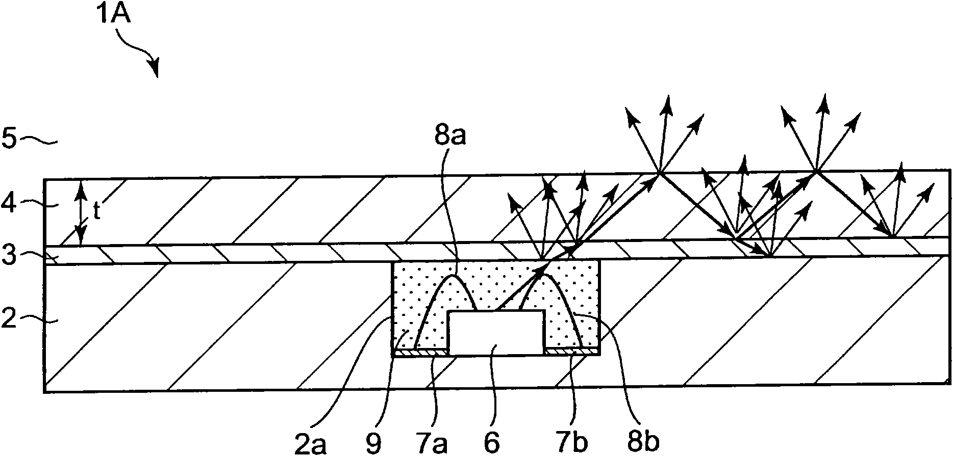
[0095] figure 1 It is a cross-sectional view of the lighting device according to the first embodiment of the present invention. exist figure 1 In , light traveling in the light guide layer is schematically indicated by arrows, and this is the same in each of the following embodiments.

[0096] Such as figure 1 As shown, the lighting device 1A has a substrate 2 . The substrate 2 is a substantially inflexible synthetic resin substrate, an easily bendable thin-film synthetic resin substrate, a metal substrate, or the like.

[0097] A recess 2 a is formed on the substrate 2 from the surface thereof, and a bare chip (light source) 6 forming an optical element is accommodated in the recess 2 a and fixed by an adhesive or the like. The electrode layer provided on the bare chip 6 and the conductive patterns 7a, 7b formed on the bottom surface of the concave portion 2a are individually connected by wires 8a, 8b made of thin wires (wire bonding). The inside of the concave portion 2...


PUM


Abstract

To provide a thin illumination device capable of efficiently utilizing light emitted from a light source, and an input device equipped with the illumination device. [Means for Solution] A recess portion 2a is formed in a substrate 2 to accommodate a light emitting element 6 so as to be sealed with a sealant 9. A light guide layer 4 formed of a thin transparent resin film is fixed onto the substrate 2 via an adhesive layer 3 to realize an illuminating device 1A with a thin structure. The light emitted from the light emitting element 6 is irradiated into the light guide layer 4 via the sealant 9 and the adhesive layer 3. The light fully reflecting on the boundary surfaces between the light guide layer 4 and the adhesive layer 3, and between the light guide layer 4 and the air layer 5 passes inside the light guide layer 4. Then the light which has not fully reflected leaks outside from the surface of the transparent resin film which forms the light guide layer 4. This makes it possible to illuminate the surface of the illumination device 1A entirely with brightness.

Description

technical field [0001] The present invention relates to an illuminating device for illuminating operation parts and the like of various electronic devices, and particularly relates to a thin illuminating device capable of effectively utilizing light emitted from a light source, and an input device having the illuminating device. Background technique [0002] In various electronic devices such as audio equipment or portable electronic equipment, a light guide member is generally provided to guide light emitted from a light source such as an LED to the operation surface, and the operation buttons or engraved on the operation surface are guided by the above-mentioned light. Illuminate the fixed character or number display on the operation surface. [0003] Conventionally, this type of lighting device has a structure in which a lighting member such as an acrylic plate is attached to the back side of an operation surface of an electronic device, and light from a light source is g...

Claims


Application Information

Patent Timeline
Patent Type & Authority Applications(China)
IPC IPC(8): F21S2/00F21V8/00G02B6/00G09F13/18H01H9/18H01H13/02F21Y101/02
CPCG02B6/002H01H13/83G02B6/0018H01H2219/062G02B6/0031G02B6/0028H01L33/58H01L2924/181H01L2224/48091H01L2924/00012H01L2924/00014
Inventor 伊藤直树冈本淳
Owner ALPS ALPINE CO LTD
Why Eureka
Try Eureka