Guide rails

A technology of compact racks and guide rails, which is applied in cabinets for storing books, household appliances, applications, etc. It can solve the problems of poor guide rail effect, unsafe use, and influence on appearance and cleanliness, so as to improve installation accuracy, safe and reliable use, and compactness well-structured effects

Inactive Publication Date: 2009-11-25
朱建华
View PDF0 Cites 5 Cited by
  • Summary
  • Abstract
  • Description
  • Claims
  • Application Information

AI Technical Summary

Problems solved by technology

The disadvantage of this fixing method is that the expansion screw 4' on the pressing part 3' is far away from the guide rail 2', and the force arm between the screw and the guide rail is relatively large, so that the effect of fixing the guide rail is poor; What is more important is that the auxetic expansion screw 4' is fastened. When the screw is tightened, the exposed screw head 41' is likely to collide with the human body or other objects, causing scratches and unsafe use. Moreover, the exposed screw head 41' 'It also makes the upper surface of the guide rail seat uneven, which affects the overall appearance and cleanliness
[0004] In addition, the traditional guide rail is directly welded on the guide rail seat. Due to the high temperature during welding, it is easy to cause thermal deformation of the U-shaped sides of the guide rail seat and the two folded edges, which in turn affects the installation accuracy and performance of the guide rail. Moreover, because the guide rail The long groove on the seat is blocked by the folded edges on both sides and the space is small, which makes the movable space limited when the guide rail is welded to the guide rail seat, and it is very inconvenient to operate; on the other hand, the guide rail is directly welded to the bottom surface of the guide rail seat, and the guide rail From the upper part, there will be obvious welding scars along both sides of the guide rail, which will affect the cleanliness and beauty of the guide rail

Method used


Image

  • Guide rails
  • Guide rails
  • Guide rails

Examples


Embodiment Construction

[0019] The present invention will be further described in detail below in conjunction with the accompanying drawings and embodiments.

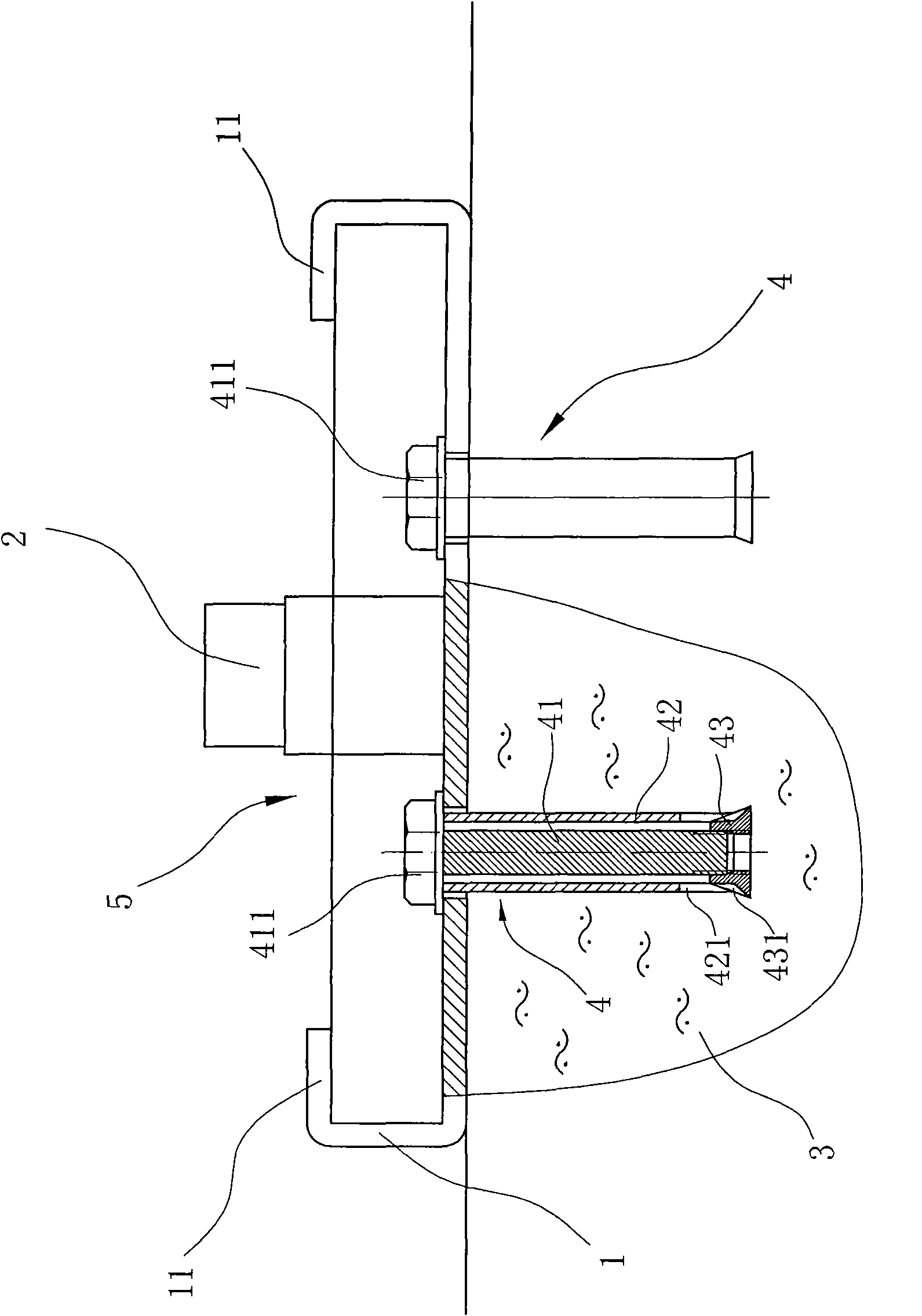
[0020] Such as figure 1 As shown, it is a schematic diagram of the installation structure of the guide rail in this embodiment. The guide rail includes a guide rail seat 1 connected to the foundation 3 and a guide rail 2 connected to the guide rail seat 1 for erecting rollers.

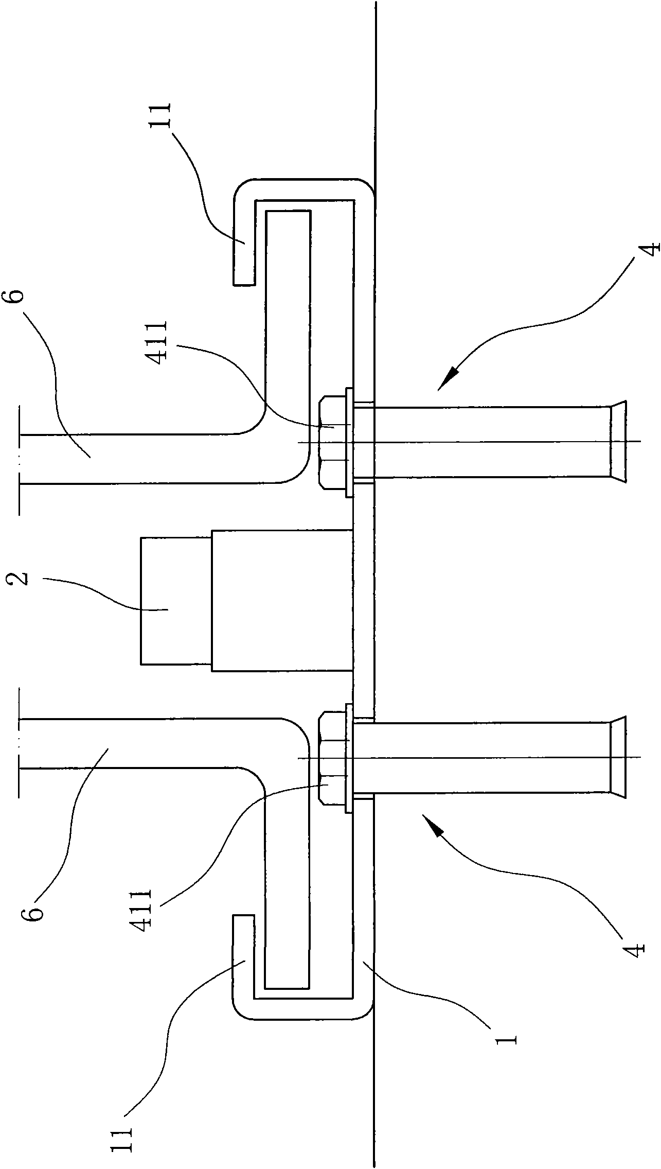
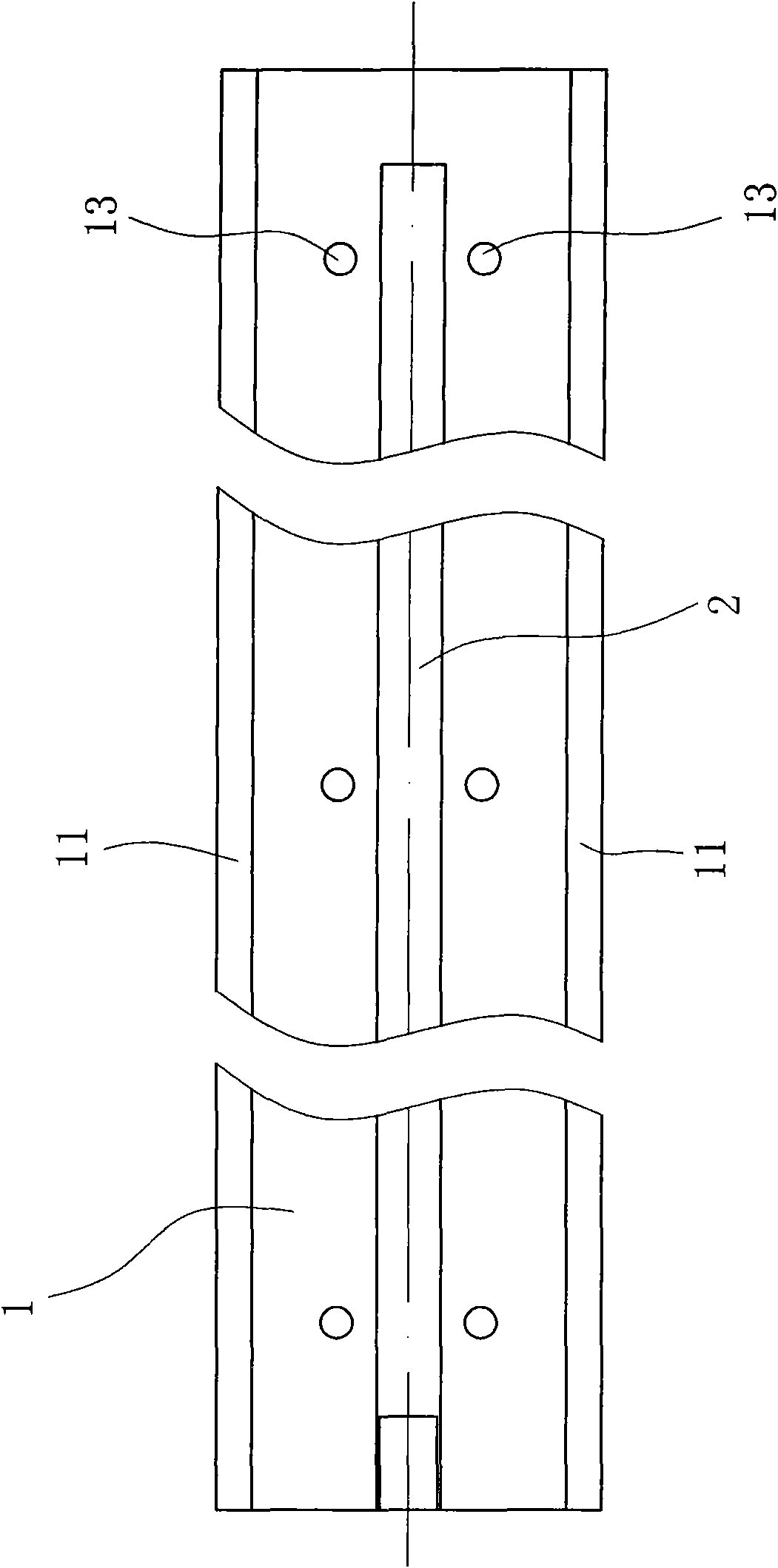
[0021] Such as figure 2 , image 3 with 4 As shown, the bottom surface of the guide rail seat 1 is provided with a plurality of groups of small holes 13 for screw or bolt installation which are located on both sides of the guide rail 2 and are aligned with each other. In order to avoid damage to the exposed screw heads, in this embodiment A compression expansion screw assembly 4 is installed in the hole 13 . The expansion screw 4 includes a screw 41 with a hexagonal head 411 connected to the head, an expansion sleeve 42 sleeved outside the screw 41 and a conical ...


PUM


Abstract

Guide rails of a serried shelf comprise a base of guide rails and guide rails installed on ground base and mutually fixedly connected together, wherein the base section of the base of guide rails is U-shaped, the ends at both sides are respectively inwards bended to form two hems, a long groove is formed between the two hems, and the guide rails are positioned in the long groove and is fixedly connected with the bottom face of the base of guide rails. The guide rails are characterized in that the bottom face of the base of guide rails is further provided with small holes respectively abutted upon both sides of the guide rails, and the small hole is internally provided with a pressure-expandable plug bolt assembly for locating the guide rails. Compared with the existing technology, in the invention, bolts for fixing the base of guide rails are installed at both side abutted upon the guide rail so that the tension arm between the bolts and the guide rails becomes smaller; the compressing structure of the base of guide rails is reasonable, the pressure effect is good, and the guide rails are easily adjusted on a same horizontal surface, thereby being capable of improving the installation accuracy of the guide rails, and ensuring that roller wheels roll on the guide rails safely and steady.

Description

technical field [0001] The invention relates to a guide rail positioning structure, in particular to a fixing structure for a compact shelf guide rail. Background technique [0002] At present, archives, libraries and museums are widely using mobile shelves to hold various archives, books, cultural relics and other items. Usually, the mobile compact rack can be moved back and forth by hand or electric operation. The chassis of the compact rack is connected with a load-bearing beam with rollers, and the rollers can cooperate with the guide rails to realize the movement of the compact rack. In order to ensure that the rollers can roll along the guide rails, guide rails are generally welded on the guide rail seats, and the rollers are mounted on the guide rails. [0003] In the existing technology, such as Figure 7 As shown, the main body section of the guide rail seat 1' is U-shaped and the end edges on both sides are respectively bent inward to form two folded edges 11', an...

Claims


Application Information

Patent Timeline
Patent Type & Authority Applications(China)
IPC IPC(8): A47B63/00
Inventor 朱建华
Owner 朱建华
Why Eureka
Try Eureka