
Pneumatic painting apparatus with spray gun, heater device, and dehumidifier/drier device

A spraying device, dehumidifier technology, applied in the direction of spraying devices, liquid spraying devices, chemical instruments and methods, etc., can solve the problems of inconvenient replacement, non-renewable fluid particle mixture optimization, difficult to realize, etc.

Inactive Publication Date: 2009-11-25
WALMEC
View PDF6 Cites 8 Cited by
  • Summary
  • Abstract
  • Description
  • Claims
  • Application Information

AI Technical Summary

Problems solved by technology

[0024] The second problem is found, even if partially solved, in spraying equipment with conventional spray guns, which in principle involves the need to have a volume of air under pressure which arrives in a substantially dehumidified state before mixing with the paint spray gun
In principle, it appears that the obvious problems associated with the solution US5214740 (Carroll) could be solved by combining similar solutions, however, the solution proposed by WO2006 / 016256 (Milli) appears to be complex, difficult to implement, and difficult to achieve in conventional types of pneumatic Inconvenient replacement in spraying equipment
[0050] Also, for both solutions, the use of a fluid consisting essentially of a gas mixture, despite heating, is believed to be without dehumidification, which, from a practical point of view, significantly reduces the effect of the application
[0051] In EP1332784 (Milli) although a dehumidifier is provided, it does not appear to be regenerable and appears to be optimized for fluid particle mixtures

Method used


Image

  • Pneumatic painting apparatus with spray gun, heater device, and dehumidifier/drier device
  • Pneumatic painting apparatus with spray gun, heater device, and dehumidifier/drier device

Examples


Embodiment Construction

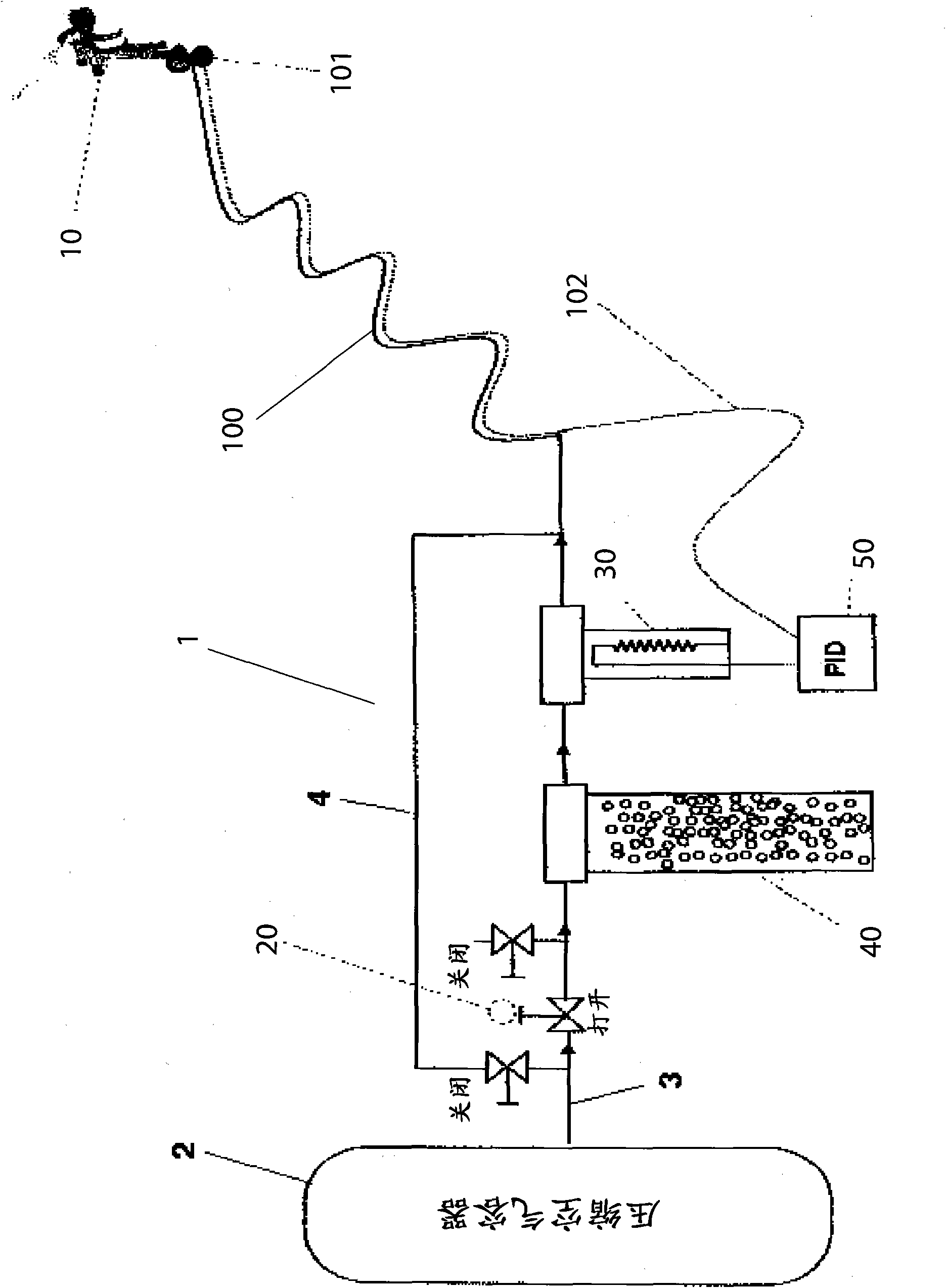
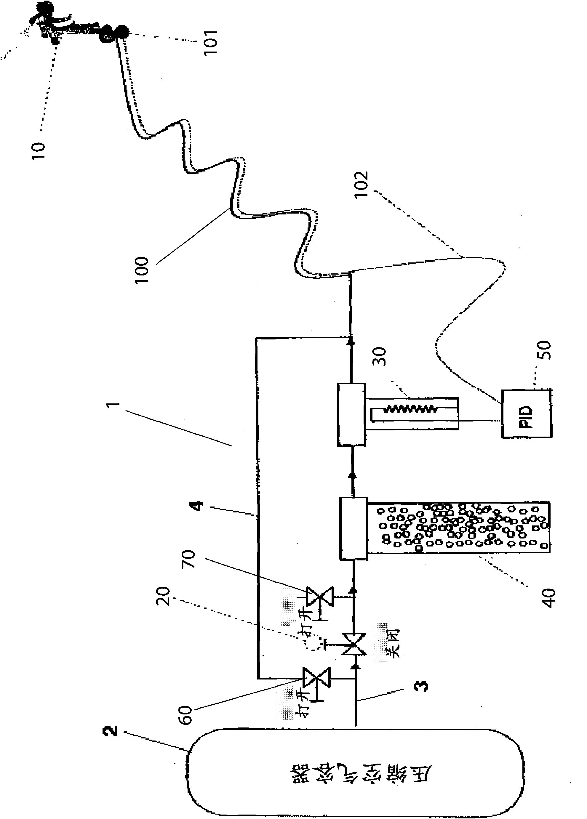
[0075] The object of the present invention is a spraying device 1 of the pneumatic type having a spray gun 10 with a heater device 30 of air flow under pressure and a dehumidifier / dryer 40 provided with a regeneration device 4 containing an adsorbent containing In the dehumidifier / dryer 40, it is used to fluidize the coating during application to the support.

[0076] Such as figure 1 As shown, the spraying apparatus 1 comprises a conventional compressor unit (not shown) fed to a compressed air container 2 . The compressed air container 2 has an outlet for a compressed air flow which is fed into the compressed air flow circuit 3 and conveyed towards at least one spray gun 10 . The circuit 3 is activated by a solenoid valve 20 located between the supply pipe 100 of the spray gun 10 and the compressed air container 2 , passing at least one heater device 30 for the treatment air flow and then conveyed through the supply pipe 100 of the spray gun 10 . In this case there is a te...


PUM


Abstract

The invention relates to a pneumatic painting apparatus with a spray gun, a heater device and a a de-humidifier / drier device. The invention relates to a pneumatic type painting apparatus with the use of at least one spray gun.

Description

technical field [0001] The invention relates to a spraying device of the pneumatic type using at least one spray gun. Background technique [0002] Spray guns are well known. Together with the compressor unit, they form part of an installation for the pneumatic painting of surfaces, such as the bodywork of a motor vehicle. [0003] In principle, spraying equipment for decorative or protective purposes consists of the following components: [0004] - compressor / pump sets and associated vessels, mainly movably supported by their own frame, with associated supply and control units; [0005] - flexible supply pipe between the compressor unit and the spray gun; [0006] - Pneumatic spray gun connected to the compressor unit through a flexible supply tube; the sprayed product is atomized by the action of compressed air through the gun, either by means of a cup placed above (for gravity) or cup placed below (for inhalation) to supply said spray product; [0007] -The cup or co...

Claims


Application Information

Patent Timeline
Patent Type & Authority Applications(China)
IPC IPC(8): B05C5/02B05C11/10B05B7/02B05B7/30
CPCB05B7/162B01D2259/4009B01D53/261B01D2253/106
Inventor 扎内蒂·保罗
Owner WALMEC
Learn More