Pressure reducing valve for gas

A pressure reducing valve and gas technology, applied in the direction of fluid pressure control, balance valve, valve device, etc., can solve the problems of large-scale main body and increase in the number of parts, and achieve cost reduction, cost reduction, and prevention of main body temperature reduction. Effect

Active Publication Date: 2009-11-25
HITACHI ASTEMO LTD
View PDF1 Cites 3 Cited by
  • Summary
  • Abstract
  • Description
  • Claims
  • Application Information

AI Technical Summary

Problems solved by technology

[0006] In addition, in order to prevent the temperature of the main body from excessively dropping due to decompression, in the pressure reducing valve for gas disclosed in Patent Document 1, a recess provided on the side of the main body and a valve attached to the main body so as to block the recess are used. The cover plate forms the hot water passage and guides the engine cooling water to the hot water passage, however, the main body is enlarged in order to ensure the passage volume, and the number of parts increases due to the need for the cover plate

Method used


Image

  • Pressure reducing valve for gas
  • Pressure reducing valve for gas
  • Pressure reducing valve for gas

Examples


no. 1 example

[0046] Figure 1 to Figure 11 A first embodiment of the invention is shown.

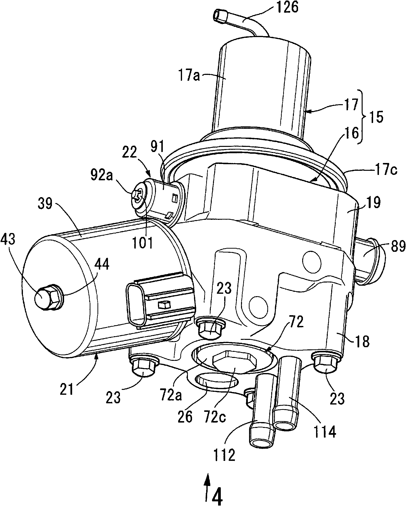
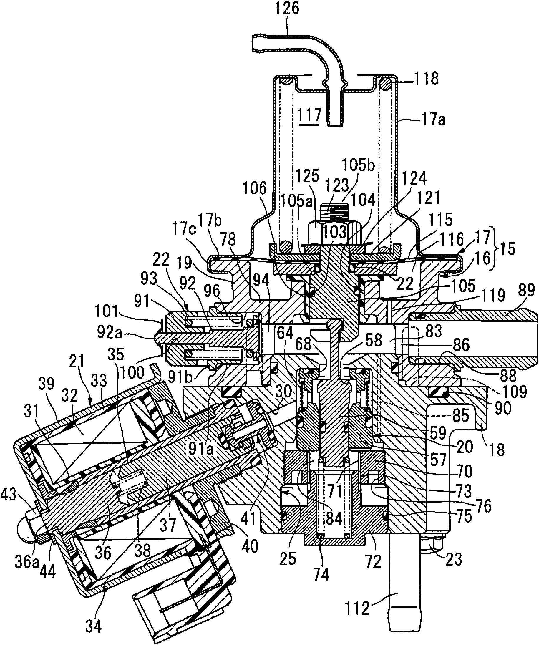
[0047] First, in figure 1 Among them, the pressure reducing valve for gas is used to depressurize compressed natural gas as fuel gas and supply it to an engine (not shown). The main body 16 formed by joining the second main body parts 19 with each other; and the diaphragm cover 17 joined to the main body 16, in which the valve mechanism 20 is accommodated (refer to figure 2 ), and is equipped with an electromagnetic cut-off valve 21 and a relief valve 22.

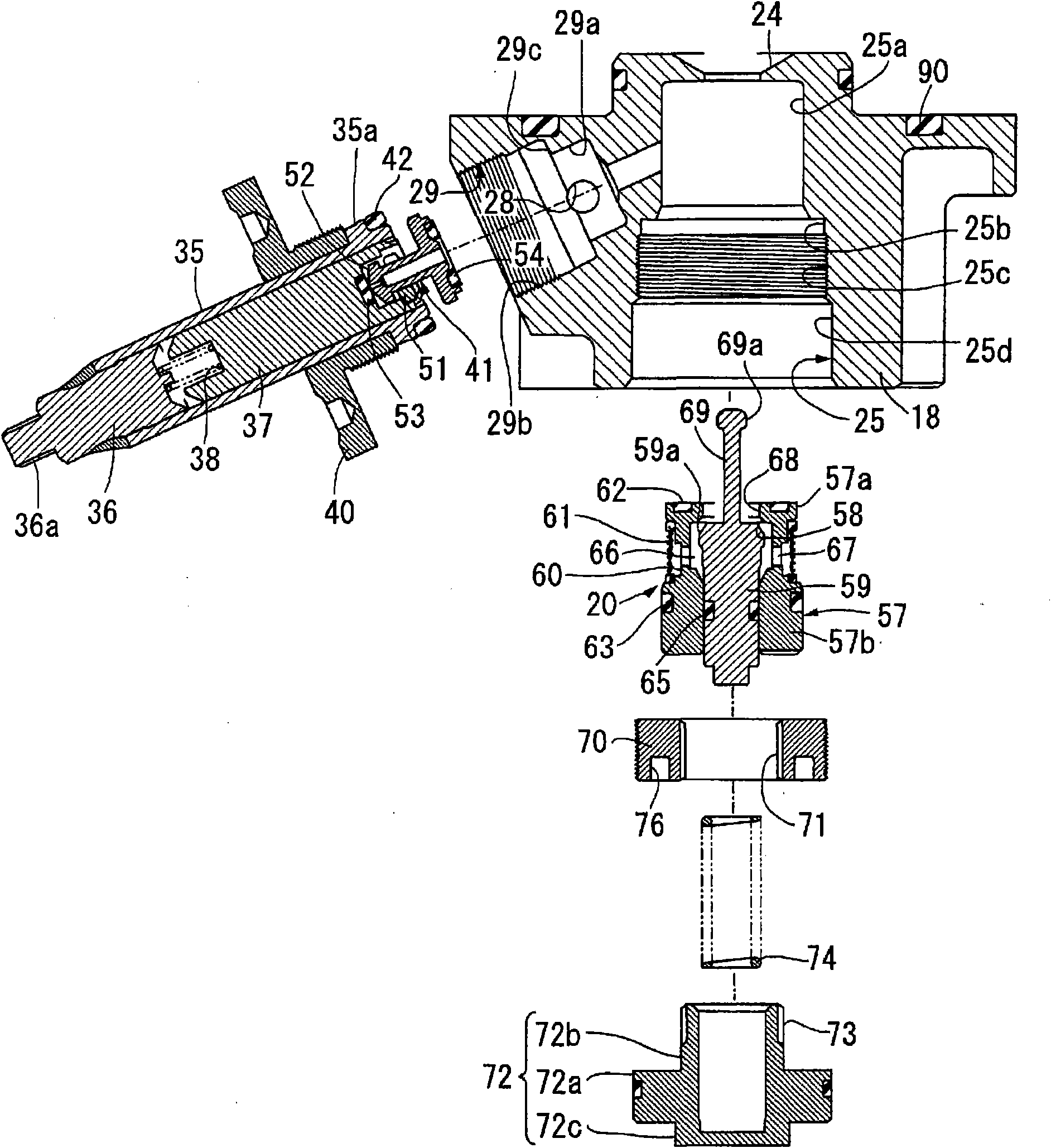
[0048] exist figure 2 Among them, the main body 16 is composed of a plurality of main body parts with different strengths (in this embodiment, a high-strength first main body part 18 and a low-strength second main body part 19) overlapping up and down and using multiple (for example, four) ) Bolts 23, 23... are formed by jointing each other. The first main body part 18 is formed by cutting and forming, for example, a drawn material made of a...

no. 2 example

[0119] Figure 12 and Figure 13 A second embodiment of the present invention is shown.

[0120] First, in Figure 12 Among them, the housing 15' of the pressure reducing valve for gas is composed of a main body 16' and a diaphragm cover 17. The main body 16' is formed by joining a first main body part 18' and a second main body part 19', and the membrane The sheet cover 17 is joined to the main body 16 ′, and the valve mechanism 20 is accommodated in the main body 16 ′, and an electromagnetic shutoff valve 21 and a relief valve 22 are arranged therein.

[0121] The main body 16' is composed of a plurality of main body parts with different strengths (in this embodiment, a high-strength first main body part 18' and a low-strength second main body part 19') overlapping up and down and utilizing four screws 23, 23 ... are formed by jointing each other. The first main body part 18' is formed by cutting a drawn material made of aluminum alloy, or is formed by cutting corners aft...


PUM


Abstract

A pressure reducing valve for gas has a valve mechanism. The valve mechanism has a valve body having a valve hole opened at its center and communicating with a low-pressure path and a low-pressure chamber and can be seated on a valve seat facing a valve chamber communicating with a high-pressure chamber. The valve mechanism is received in a body with the valve body connected to a pressure receiving member operating according to pressure of the low-pressure path and low-pressure chamber. The body (16) is constructed by joining body members (18, 19) having different strength.The entire portions of high-pressure paths (30, 64) are formed in the body member (18) having higher strength than the body members (19). Some of the low-pressure paths (85, 86, 94, 119) and low-pressure chambers (83, 84, 116) are formed in the body member (19), which has lower strength. The construction reduces costs of the pressure reducing valve.

Description

technical field [0001] The present invention relates to a pressure reducing valve for gas. The valve mechanism of the pressure reducing valve for gas has a valve hole communicating with a low-pressure passage and a low-pressure chamber in the central part, and the valve mechanism has a valve core capable of seating on a valve seat. , the valve seat faces the valve chamber communicated with the high-pressure passage, the valve core of the valve mechanism is connected to the pressure component and the valve mechanism is accommodated in the main body, the pressure component is in the low-pressure passage and The low-pressure chamber operates under pressure. Background technique [0002] Such a pressure reducing valve for gas is known in Patent Document 1, for example. [0003] Patent Document 1: Japanese Patent Laid-Open No. 2002-180907 [0004] However, in the decompression valve for gas disclosed in the above-mentioned Patent Document 1, the main body is composed of a singl...

Claims


Application Information

Patent Timeline
IPC IPC(8): F16K17/04F02M21/02F16K31/06F16K49/00
CPCY02T10/32G05D16/0663F02M21/0239F02M21/0233Y02T10/30Y10T137/6579Y10T137/6606Y10T137/7757Y10T137/7809Y10T137/7823Y10T137/7825
Inventor 山本博晓中岛要治斋藤芳夫千叶豊
Owner HITACHI ASTEMO LTD
Why Eureka
Try Eureka