
Chopper-stabilized instrumentation amplifier and method for impedance measurement

A technology of instrument amplifiers and gain amplifiers, applied in the direction of amplifiers, differential amplifiers, amplifier types, etc.

Active Publication Date: 2012-08-15
MEDTRONIC INC
View PDF4 Cites 0 Cited by
  • Summary
  • Abstract
  • Description
  • Claims
  • Application Information

AI Technical Summary

Problems solved by technology

This ripple can make it difficult to implement chopper-stabilized designs in low-power applications

Method used


Image

  • Chopper-stabilized instrumentation amplifier and method for impedance measurement
  • Chopper-stabilized instrumentation amplifier and method for impedance measurement
  • Chopper-stabilized instrumentation amplifier and method for impedance measurement

Examples


Embodiment Construction

[0030] In general, the instrumentation amplifiers described in this disclosure may be configured for very low power applications. For example, implantable medical devices may be characterized as requiring limited electrical resources to operate continuously for months or years. Therefore, sensing and therapy circuits are usually designed to consume only very low levels of power. As an example, as shown in this disclosure, a sensor circuit incorporating an instrumentation amplifier may require less than 2.0 microamperes of supply current, more preferably less than 1.0 microamperes, to operate. In some embodiments, the sensor circuit may draw a supply current in the range of about 100 nanoamps to about 1.0 milliamps. This sensor may generally be referred to as a micropower sensor. Although medical devices are described for purposes of illustration, micropower sensors may be used in medical and non-medical test and measurement applications. In each case, the sensor may need to...


PUM


Abstract

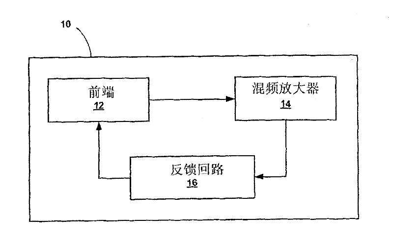
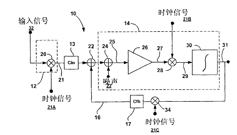
This disclosure describes a chopper stabilized instrumentation amplifier. The amplifier is configured to achieve stable measurements at low frequency with very low power consumption. The instrumentation amplifier uses a differential architecture and a mixer amplifier to substantially eliminate noise and offset from an output signal produced by the amplifier. Dynamic limitations, i.e., glitching, that result from chopper stabilization at low power are substantially eliminated through a combination of chopping at low impedance nodes within the mixer amplifier and feedback. The signal path of theamplifier operates as a continuous time system, providing minimal aliasing of noise or external signals entering the signal pathway at the chop frequency or its harmonics. The amplifier can be used in a low power system, such as an implantable medical device, to provide a stable, low-noise output signal.

Description

technical field [0001] This invention relates to amplifiers, and more particularly to instrumentation amplifiers for precise signal measurements. Background technique [0002] Instrumentation amplifiers are used to accurately measure a wide variety of test and measurement signals. For example, a medical instrumentation amplifier might be configured to measure physiological signals such as electrocardiogram (ECG), electromyography (EMG), electroencephalogram (EEG), pressure, impedance, and motion signals. Typically, instrumentation amplifiers are constructed as differential amplifiers with low offset, low drift, low noise, high common-mode rejection, high loop gain, and high input impedance. In many cases, instrumentation amplifiers may require careful matching and fine-tuning of circuit components to achieve high accuracy. [0003] Instrumentation amplifiers may be constructed using discrete switched capacitor structures that obtain discrete signal samples. However, the ...

Claims


Application Information

Patent Timeline
Patent Type & Authority Patents(China)
IPC IPC(8): H03F3/38H03F3/45H03F1/26H03F3/387A61B5/308
CPCH03F2203/45212A61B5/7228H03F2203/45138H03F3/45744H03F2200/372A61N1/36521H03F1/26H03F2200/252H03F2203/45028H03F2200/375H03F2203/45551A61B5/0428A61N1/3704H03F2200/271H03F2200/153H03F3/45192H03F3/45183H03F2203/45534H03F3/387H03F2203/45512H03F2200/261A61B5/04004A61B5/103A61N1/3702H03F3/45968A61B5/0002A61B2560/0209A61B5/7217H03F3/45475H03F2203/45396A61B5/7203A61N2001/083H03F2203/45264A61B5/053A61B5/30H03F3/38
Inventor T·J·丹尼森W·A·桑塔
Owner MEDTRONIC INC
Learn More