Electric chain saw

An electric chain saw and motor shaft technology, which is applied to chainsaws, sawing equipment, sawing machine devices, etc., can solve the problems of operator danger, disadvantageous miniaturization of electric chain saws, complex structure, etc. The effect of miniaturized design and simple overall structure

Active Publication Date: 2009-12-02
SUZHOU KINGCLEAN PRECISION MACHINERY
View PDF0 Cites 12 Cited by
  • Summary
  • Abstract
  • Description
  • Claims
  • Application Information

AI Technical Summary

Problems solved by technology

However, the brake devices installed in the electric chainsaws currently on the market usually have only one brake unit. Once the brake unit fails and is damaged, the user can no longer apply the brakes, and the safety of the electric chainsaw is still not improved.
Moreover, the existing electric chain saw braking devices often use mechanisms such as clutches, levers, and gears connected to the motor shaft to brake the motor. Not only is the braking action slow, but the structure is complex and there are many parts, which is not conducive to the miniaturization of the electric chain saw. requirements
[0003] On the other hand, during the normal shut-off process of the existing electric chain saw, because the chain saw blade cannot stop immediately under the action of inertia, there is still the possibility of bringing danger to the operator.
In order to reduce the possibility of this danger and ensure the safety of the operator, the electric chainsaw must be designed with a brake device that can also realize the braking action during its normal shutdown process; however, the brake device installed in the current electric chainsaw All of them realize the emergency braking function, that is, they all brake the motor shaft by forcibly cutting off the power supply circuit of the motor first, but it seems powerless to brake the motor shaft when the electric chain saw is normally turned off.

Method used


Image

  • Electric chain saw
  • Electric chain saw
  • Electric chain saw

Examples


Embodiment

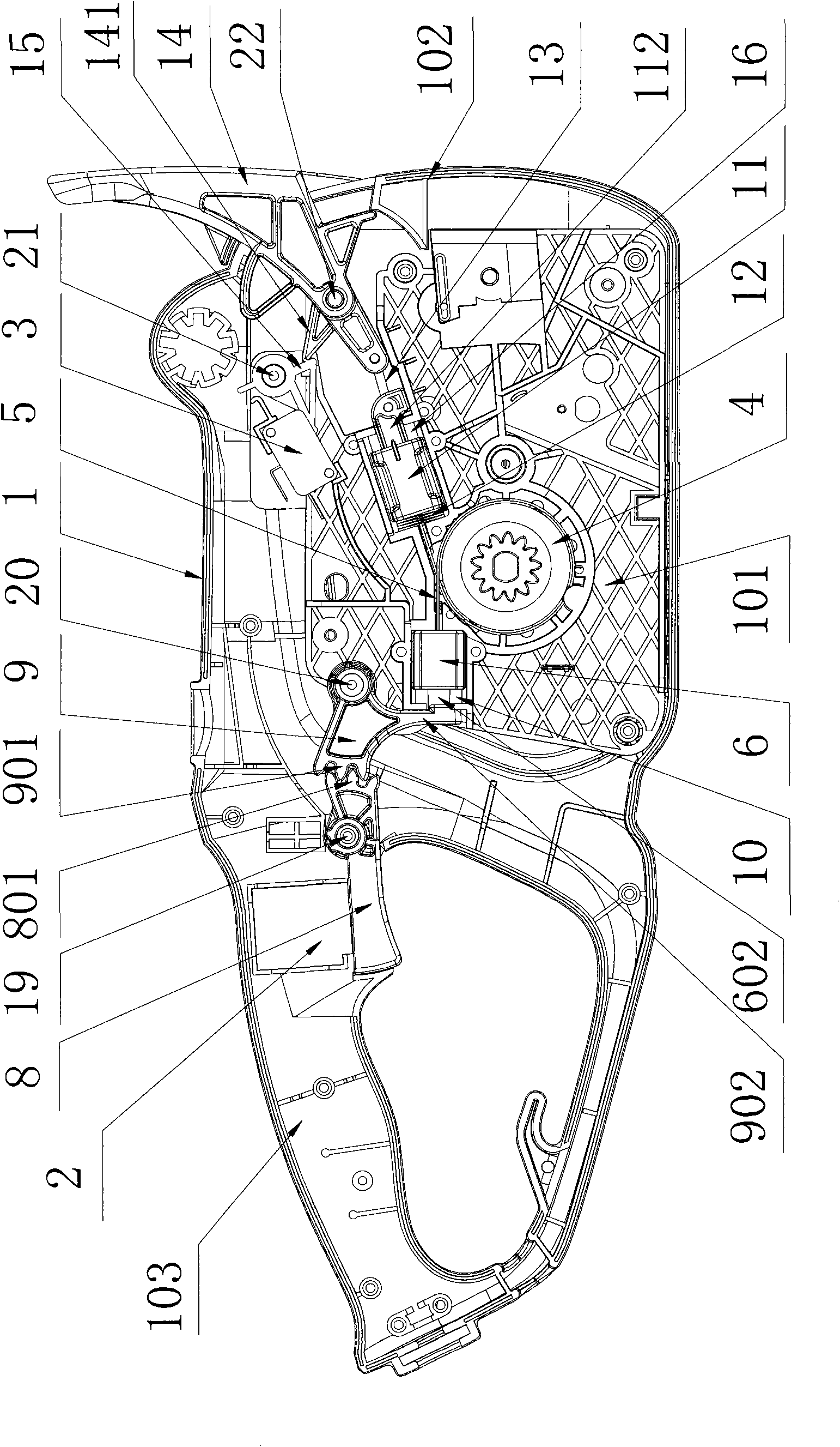
[0052] Embodiment: The technical solution of the present invention will be further described below in conjunction with the accompanying drawings through the embodiments.

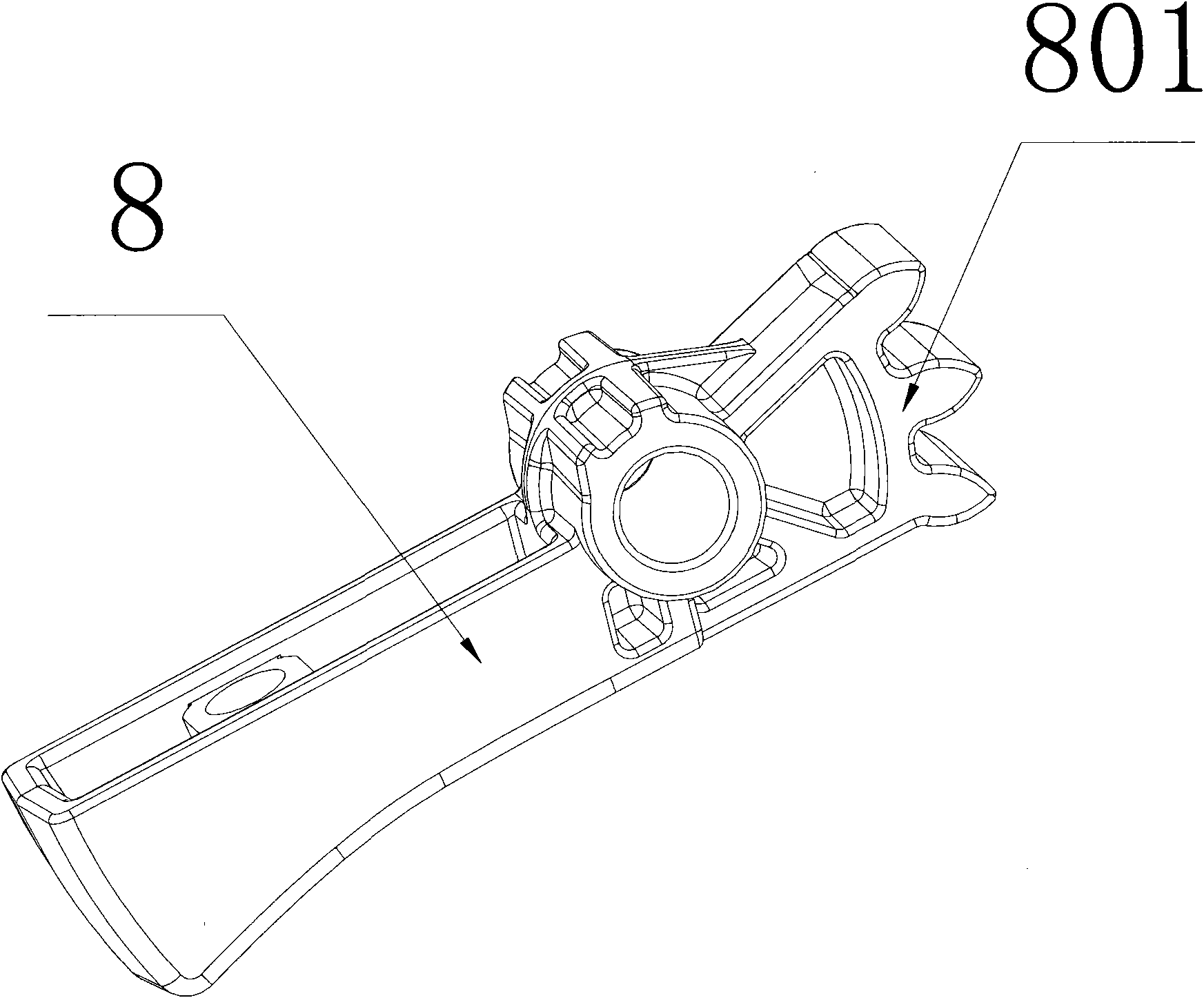
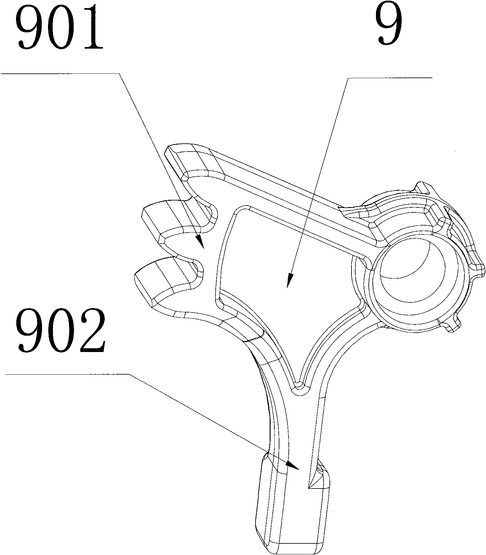
[0053] Such as figure 1 Shown is a kind of specific embodiment of electric chain saw of the present invention, and this electric chain saw comprises casing 1, the motor that is located in casing 1, the chain saw blade (not shown in the drawing) driven by motor shaft and installation The brake device in the casing 1, the casing 1 is composed of the casing body 101 and the front and rear handles 102, 103 which are integrated with the casing body 101; the rear handle 103 is provided with a main power switch 2, and the casing The motor and the protective power switch 3 are arranged in the main body 101 , and the motor, the main power switch 2 and the protective power switch 3 are connected in series. The brake device is composed of a brake drum 4, a brake band 5, a first brake unit and a second brake unit; the ...


PUM


Abstract

The invention discloses an electric chain saw, which comprises a shell, a motor and a brake device thereof, wherein the motor and the brake device are arranged in the shell. The brake device comprises a brake drum and a brake band, wherein the brake drum is sleeved on a motor shaft and rotates along with the motor shaft; and the brake band is sleeved on the outer edge of the brake drum, one end of the brake band is connected with a first brake unit, and the other end of the brake band is connected with a second brake unit. The brake device in the electric chain saw adopts two brake units which can reply two conditions of normal braking and emergency braking respectively, and when one brake unit fails, the other brake unit can implement braking, so the brake device fully meets the requirement in the aspect of service safety of the electric chain saw, and has the characteristics of quick braking, simple and convenient operation and sensitive motion; and compared with the prior electric chain saw adopting the brake mechanisms such as a clutch, a lever and a gear, the electric chain saw of the invention has the advantages of simple integral structure and few parts, and is more favorable for miniaturized design of the electric chain saw.

Description

technical field [0001] The invention relates to an electric chain saw. Background technique [0002] Because the chain saw blade on the electric chain saw will recoil toward the operator due to accidental collision during use, which will bring danger to the operator, so the electric chain saw is generally equipped with a brake device. However, the brake devices installed in the electric chainsaws currently on the market usually have only one brake unit. Once the brake unit fails and is damaged, the user can no longer apply the brakes, and the safety of the electric chainsaw still cannot be improved. Moreover, the existing electric chain saw braking devices often use mechanisms such as clutches, levers, and gears connected to the motor shaft to brake the motor. Not only is the braking action slow, but the structure is complex and there are many parts, which is not conducive to the miniaturization of the electric chain saw. requirements. [0003] On the other hand, during th...

Claims


Application Information

Patent Timeline
Patent Type & Authority Applications(China)
IPC IPC(8): B23D57/02
CPCB27B17/083
Inventor 倪祖根
Owner SUZHOU KINGCLEAN PRECISION MACHINERY
Why Eureka
Try Eureka