Transformer

A transformer and high-voltage technology, applied in the field of transformer structure improvement, can solve the problems of undetectable, flashing, insufficient voltage resistance, etc.

Inactive Publication Date: 2009-12-02
INNOLUX CORP
View PDF2 Cites 6 Cited by
  • Summary
  • Abstract
  • Description
  • Claims
  • Application Information

AI Technical Summary

Problems solved by technology

[0006] In the known technology, since the conductive terminal 118 is too close to the outlet end of the last slot of the secondary coil 130, 140, it is easy to spark (flash) due to insufficient withstand voltage due to the increase in the number of transformer turns.
In addition, the connection between the last slot of the secondary coils 130 and 140 and the conductive terminal 119 is a slanted wire suspended connection, so it is easy to be squeezed and disconnected during the assembly operation.
Furthermore, the 2 in 1 transformer technology used to drive cold cathode fluorescent lamps (Cold Cathode Fluorescent Lamp, CCFL), when applied to U-shaped or C-shaped lamps, must drive the lamps in a dual high-voltage manner, but for inverters The inverter (inverter) needs to perform current detection, because the transformer cannot detect if there is no middle tap, such as Figure 1A , 1B , 2A, 2B, and 2C, only the high-voltage ends at both ends have no middle tap structure

Method used


Image

  • Transformer
  • Transformer
  • Transformer

Examples


Embodiment Construction

[0064] In order to describe the display method of the display and the display of the present invention, the following detailed examples are used to illustrate it, but the scope of rights of the present invention is not limited to the following examples.

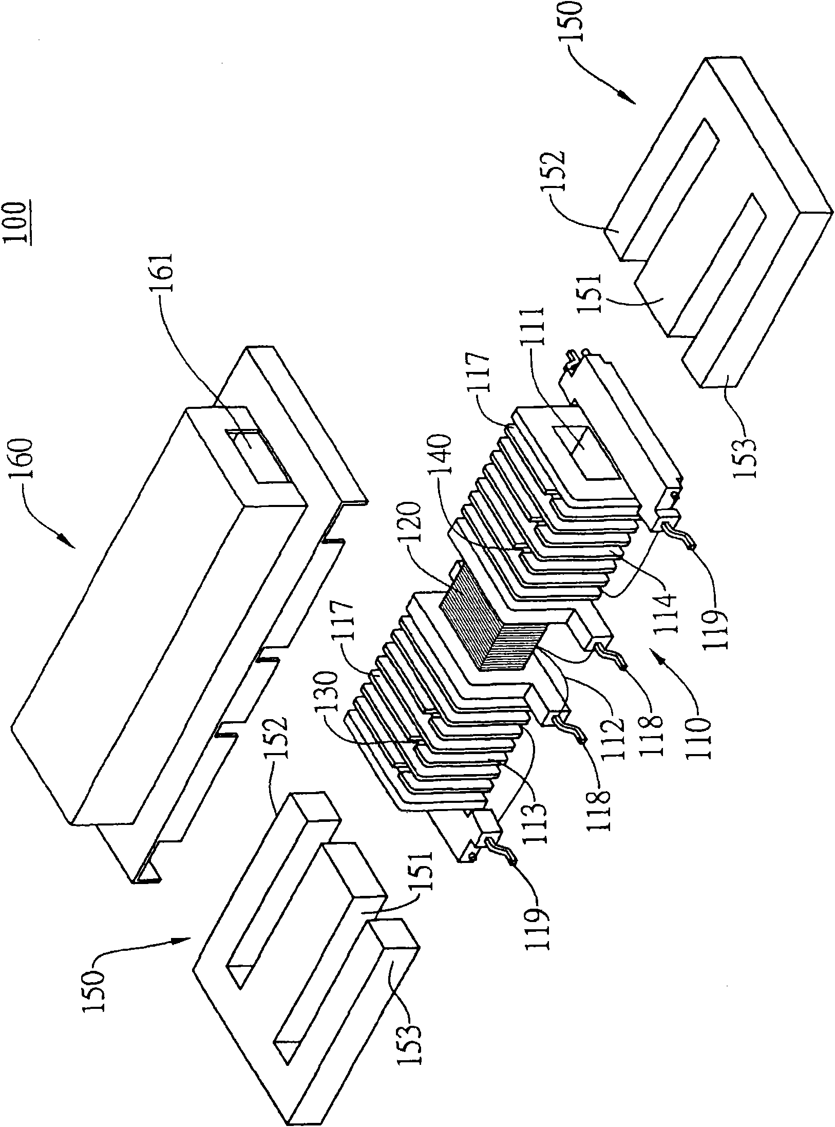
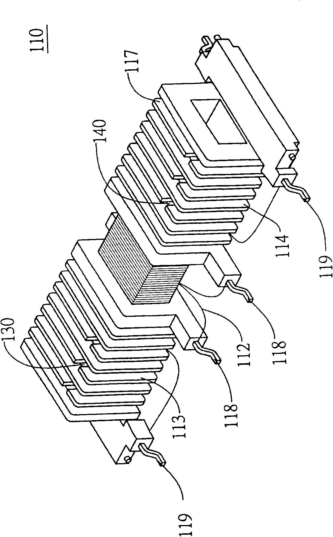
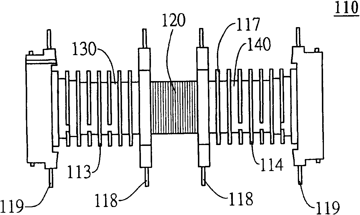
[0065] Please refer to Figure 3A , 3B , 4A, 4B, and 4C are schematic diagrams of the structure of a 2 in 1 transformer used to drive cold cathode fluorescent lamps (Cold Cathode Fluorescent Lamp, CCFL) in a preferred embodiment of the present application, a top view of a 2 in 1 transformer, and a 2 in 1 transformer Side view and front view of 2 in 1 transformer. As shown in Figures 3A, 3B, 4A, 4B, and 4C, the transformer structure includes one or two sets of primary coils connected in parallel, and two sets of independent secondary coils drive two AC / DC voltage converters respectively. Using this The AC / DC voltage converter can respectively drive a Cold Cathode Fluorescent Lamp (CCFL). The structure of the transformer 200...


PUM


Abstract

The invention provides a transformer with improved structure, which utilizes partition boards which are in unequal interval arrangement to form a plurality of coil chutes, thereby avoiding sparking (flashing) caused by under pressurization. The transformer comprises a coil frame, a primary coil, a secondary coil and an iron core assembly, wherein the coil frame is internally provided with a hollow channel and externally provided with a primary coil region and a secondary coil region; the center of the primary coil region is provided with an annularly wound center partition board; the secondary coil region comprises a plurality of annular heaves and the partition boards which are in unequal interval arrangement to form the plurality of coil chutes; the side of the coil frame is provided with a plurality of first pins and second pins, the first pins are arranged at a place adjacent to the primary coil region, and the second pins are arranged at two opposite sides of the coil frame. The primary coil is wound on the primary coil region of the coil frame, and the joint of the primary coil is connected to the first pins. The secondary coil is wound on the secondary coil region of the coil frame, and the joint of the secondary coil is connected to the second pins. The secondary coil is electromagnetically coupled with the primary coil. The iron core assembly passes through the hollow channel of the coil frame and is jointed to form a loop.

Description

technical field [0001] The invention relates to an improvement of a transformer structure, and in particular to a transformer structure that utilizes partitions arranged at unequal intervals to form a plurality of winding slots, so as to avoid the phenomenon of spark jumping (flash burning) due to insufficient withstand voltage. Background technique [0002] see Figure 1A , 1B , 2A, 2B, and 2C are respectively the structural schematic diagram of a known 2 in 1 (two-in-one) transformer used to drive cold cathode fluorescent lamps (Cold Cathode Fluorescent Lamp, CCFL), the top view of the 2 in 1 transformer, and the side of the 2 in 1 transformer view and front view of the 2 in 1 transformer. As shown in Figures 1, 2A, 2B, and 2C, the transformer structure includes one or two sets of primary coils connected in parallel, and two sets of independent secondary coils drive two AC / DC voltage converters respectively. Using this AC / DC The voltage converter can respectively drive a...

Claims


Application Information

Patent Timeline
Patent Type & Authority Applications(China)
IPC IPC(8): H01F27/28H01F27/30H01F41/06
Inventor 陈世明
Owner INNOLUX CORP
Why Eureka
Try Eureka