
Active P-V characteristic correction method and device for photovoltaic component

A technology of photovoltaic modules and calibration devices, which is applied in the fields of electrical components, semiconductor devices, climate sustainability, etc., can solve the problem of complex maximum power point tracking algorithm parameter design and implementation, and cannot guarantee the global maximum power point of photovoltaic modules. Output power reduction and other issues, to achieve the effect of improving energy conversion efficiency, low cost, and simple circuit

Active Publication Date: 2012-06-13
HUAZHONG UNIV OF SCI & TECH
View PDF0 Cites 0 Cited by
  • Summary
  • Abstract
  • Description
  • Claims
  • Application Information

AI Technical Summary

Problems solved by technology

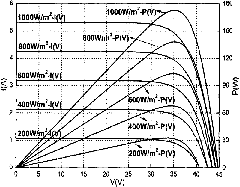
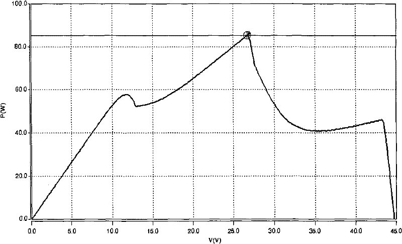
However, there are buildings and trees around a large number of photovoltaic power generation systems, and the local shadows they form on the photovoltaic modules not only cause the output power of photovoltaic modules to decrease, but also have multiple extreme points in their P-V characteristic curves, such as figure 2 Shown is the P-V characteristic curve of the photovoltaic module under partial shading conditions
Since there are multiple extreme points in the P-V characteristic curve of photovoltaic modules, the commonly used perturbation observation method and admittance increment method tend to fall into local extreme points, which cannot ensure that photovoltaic modules operate at the true global maximum power point, resulting in energy loss
[0005] In order to improve the output power of photovoltaic modules with multiple power extreme points, at present, people have carried out some research mainly on improving and proposing new global maximum power point tracking algorithms. These methods have a common problem: when photovoltaic modules appear multiple After an extreme point, these methods can only passively search for the current global maximum power point of the photovoltaic module. At this time, the power of the global maximum power point is much smaller than the current output power of the photovoltaic module. Implementation is more complicated

Method used


Image

  • Active P-V characteristic correction method and device for photovoltaic component
  • Active P-V characteristic correction method and device for photovoltaic component
  • Active P-V characteristic correction method and device for photovoltaic component

Examples


Embodiment Construction

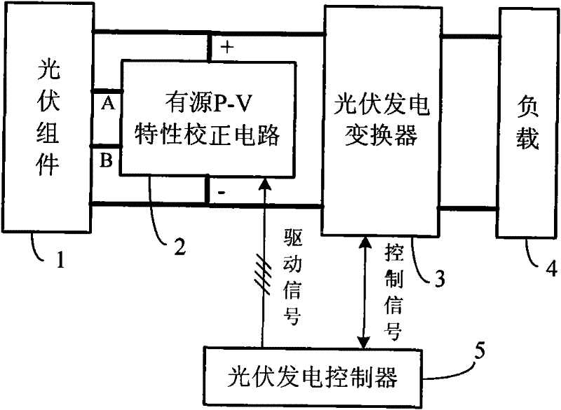
[0018] image 3 It is a block diagram of the maximum power point tracking system applying the active P-V characteristic correction circuit of the present invention, including a photovoltaic module 1, an active P-V characteristic correction circuit 2, a photovoltaic power generation converter 3, a load 4 and a photovoltaic power generation controller 5.

[0019] The internal wiring diagram of photovoltaic module 1 is as follows: Figure 4 As shown, the photovoltaic module 1 is a commercial photovoltaic module with the following characteristics: it is composed of a large number of photovoltaic cells connected in series, divided into three groups on average, and connected with three bypass diodes in parallel. The positive pole of the photovoltaic module, the cathode of a bypass diode in the middle, the anode of a bypass diode in the middle and the negative pole of the photovoltaic module are the "+" terminal, "A" terminal, "B" terminal and "-" terminal of photovoltaic module 1 re...


PUM


Abstract

The invention discloses an output P-V characteristic correction method for a photovoltaic component. The method realizes even grouping of photovoltaic battery elements connected in series in the photovoltaic component to ensure equal output voltage of each battery element group. Based on the fact that the photovoltaic battery elements are evenly divided into three groups, the invention provides the correction circuit which comprises capacitor bridge arms connected in parallel and two MOSFET bridge arms, wherein each capacitor bridge arm consists of three capacitors connected in series; the two MOSFET bridge arms have identical structures and each MOSFET bridge arm consists of a P-channel MOSFET drain electrode and an N-channel MOSFET drain electrode which are connected in series; the P-channel MOSFET drain electrode in the first MOSFET bridge arm is connected with the connection point of the two adjacent capacitors through an electrical inductance; and the P-channel MOSFET drain electrode in the second MOSFET bridge arm is connected with the connection point of the other two adjacent capacitors through another electrical inductance. The output P-V characteristic correction method corrects photovoltaic component P-V characteristic with a plurality of power extreme points under local shadow into a single power extreme point; moreover, the method adopts a maximal power point tracking method to ensure that the system operates at the maximal power point, thereby increasing the output power of the photovoltaic component.

Description

technical field [0001] The invention relates to the technical field of photovoltaic power generation, in particular to an active P-V characteristic correction method and device for photovoltaic components in a photovoltaic power supply system, which are used to ensure that the photovoltaic components have only one maximum power point under partial shadow conditions. Background technique [0002] As one of the important strategies to solve the global energy crisis and environmental problems and achieve sustainable development, photovoltaic power generation technology using clean and renewable sunlight as energy has attracted the attention of countries all over the world. [0003] In the photovoltaic power generation system, since the current-voltage (I-V) and power-voltage (P-V) characteristics of the photovoltaic module output are nonlinear and have a maximum power point, and its maximum power point changes with factors such as light and ambient temperature, in order to To m...

Claims


Application Information

Patent Timeline
Patent Type & Authority Patents(China)
IPC IPC(8): H01L31/18
CPCY02P70/50
Inventor 段善旭刘邦银康勇
Owner HUAZHONG UNIV OF SCI & TECH
Learn More