
Direct-repelling type permanent magnet rotary engine

A rotor engine and permanent magnet technology, applied in the direction of generators/motors, electrical components, etc., can solve the problems of no substantial progress in development and utilization, and productivity, and achieve the effect of increasing continuity and power enhancement

Inactive Publication Date: 2009-12-02
金银龙 +1
View PDF1 Cites 4 Cited by
  • Summary
  • Abstract
  • Description
  • Claims
  • Application Information

AI Technical Summary

Problems solved by technology

But the magnetic energy of permanent magnet is used as the utilization development of power machinery, although there is the report about (U.S. Patent No. 4.151. The development and utilization of magnetic energy as power machinery has not made substantial progress and will increase productivity.

Method used


Image

  • Direct-repelling type permanent magnet rotary engine
  • Direct-repelling type permanent magnet rotary engine
  • Direct-repelling type permanent magnet rotary engine

Examples


Embodiment Construction

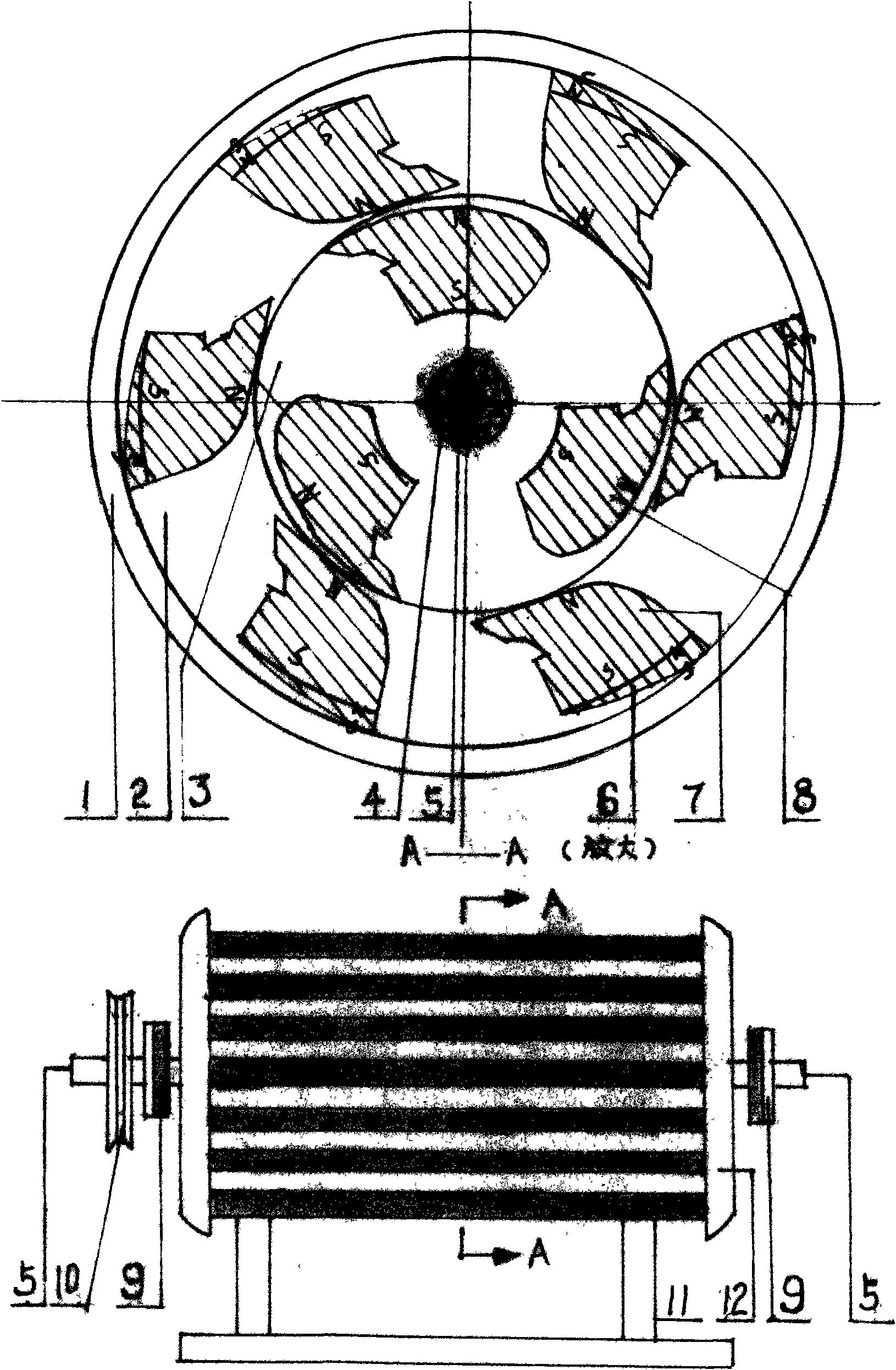
[0042] The present invention will be further described in detail in conjunction with the accompanying drawings and specific embodiments. figure 1 In the figure, body 1, stator 2, rotor 3, frame 11 and machine cover 12 are suitable for high-strength diamagnetic high-quality high-strength aluminum-magnesium alloy, which are manufactured by casting method and then mechanical cutting method or casting and pressing method. figure 1 In the figure, the rotating transmission shaft 4 is forged and then machined by using high-strength and good anti-magnetic stainless steel material with good wear resistance. figure 1 In the figure, the straight triangular magnetic block whose top side of the straight side extends forward and the small right triangular drag-reducing magnetic block that is connected to form a whole stator magnetic block 7, rotor magnetic block 8, and force-increasing balance magnetic block 6 adopt high-strength magnetic Gauss above 4000 The NdFeB alloy permanent magnet...


PUM


Abstract

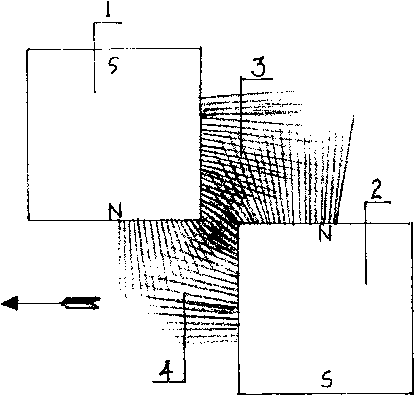
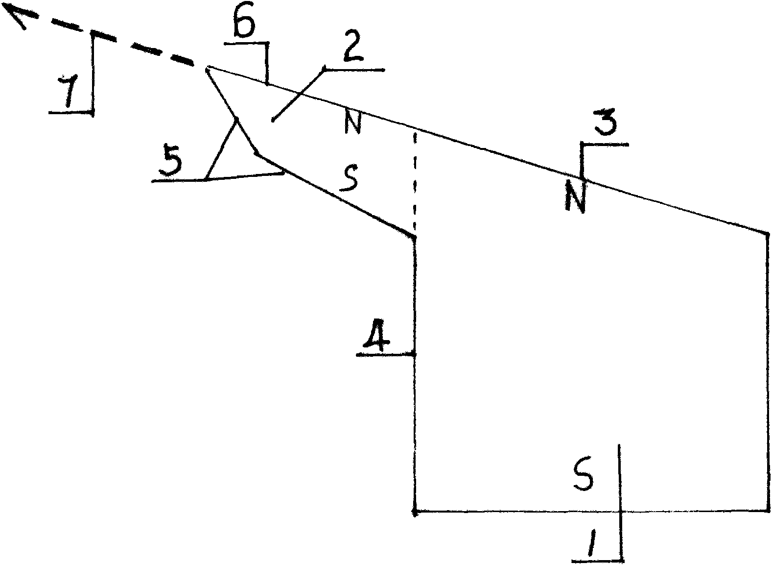
The invention relates to a rectangular triangle permanent magnet rotary engine fixed at the periphery of a stator and a rotor of diamagnetism alloy materials, in particular to a direct-repelling type permanent magnetic rotary engine driving the rotor to circularly move depending on the repulsion among same poles of a stator permanent magnet and a rotor permanent magnet and a process thereof, more particularly to an engine which works depending on the magnetic energy of the permanent magnets. The technical scheme is achieved as follows: notches are left at the straight sides of the stator rectangular triangle permanent magnet and the rotor rectangular triangle permanent magnet, a small rectangular triangle resistance-reducing magnet forwards extends along the side direction of the top ends of the straight sides; the rectangular triangle permanent magnets at the periphery of the stator are fixed at an equal angle; the bottom of the stator rectangular triangle permanent magnet is provided with a reinforcement balance magnet; the rotor is fixed at the peripheries of rotors spaced at 60 degrees by a rectangular triangle magnet with the width of 60 degrees; slope surfaces of the stator rectangular triangle magnet and the rotor rectangular triangle magnet mutually repel because of same magnetic poles. The invention is suitable for being used as a power source of an engine, an autocar, a ship, a train and aerospaceplane.

Description

Technical field: [0001] The invention relates to a permanent magnet motor in which the magnetic energy of a permanent magnet is developed into a working permanent magnet motor, in particular to a direct repulsion permanent magnet rotor motor. Background technique: [0002] my country has already successfully developed NdFeB 1 cm in 1984 3 The magnet can absorb iron and weigh 4.7 kg with high performance and high strength permanent magnet. Existing permanent magnets with higher performance have been successfully developed continuously. But the magnetic energy of permanent magnet is used as the utilization development of power machinery, although there is the report about (U.S. Patent No. 4.151. The development and utilization of this magnetic energy as a power machine has no substantial progress and will increase productivity. The development and utilization of magnetic energy will become a power machine. No matter how the technical method is adopted, the application on th...

Claims


Application Information

Patent Timeline
Patent Type & Authority Applications(China)
IPC IPC(8): H02N11/00
Inventor 金银龙
Owner 金银龙
Learn More