Automatic roll changing cutter structure of coating machine

A coating machine and cutting knife technology, applied in the field of coating machines, can solve the problems of reducing customer operability and convenience, and achieve the effect of simple and ingenious structure, less mechanical parts and simple structure

Pending Publication Date: 2021-02-26
无锡爱德旺斯科技有限公司
View PDF0 Cites 1 Cited by
  • Summary
  • Abstract
  • Description
  • Claims
  • Application Information

AI Technical Summary

Problems solved by technology

[0002] There are relatively mature unwinding and automatic rewinding and cutting devices in the coating industry, but most of them perform material reloading and cutting on one-way unwinding (commonly known as upper unwinding or lower unwinding), so the automatic reeling cutter is generally Both are designed to be cut for unwinding in one direction, which reduces the operability and convenience of customers when using

Method used


Image

  • Automatic roll changing cutter structure of coating machine
  • Automatic roll changing cutter structure of coating machine
  • Automatic roll changing cutter structure of coating machine

Examples


Embodiment

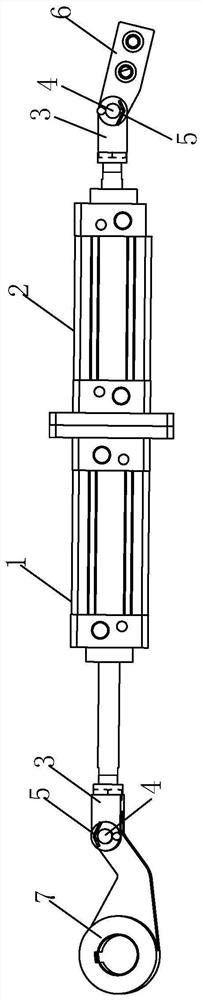
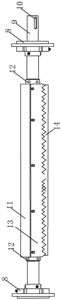
[0039] refer to Figure 1-6 , which is a cutting knife structure for an automatic roll change of a coating machine disclosed in the present invention, including a knife pushing mechanism and an idle roller cutting knife mechanism.

[0040] The idle roller cutting mechanism includes an idle roller and a semicircular knife mounting frame 11 arranged around the idle roller. The idle roller includes a shaft 9 and a bearing roller 14 arranged on the shaft 9. One end of the shaft 9 is connected with the cutting knife pushing mechanism , and driven by the knife pushing mechanism to rotate.

[0041] Both ends of the shaft rod 9 are provided with a flange bearing seat 8, and the shaft rod 9 is rotationally connected with the flange bearing seat 8, which facilitates the installation of the idler roller, forms a support for the idler roller, and facilitates the rotation of the idler roller.

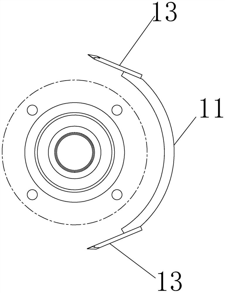
[0042] The semicircular knife mounting frame 11 is arranged in the shape of a semi-cylindrical ...


PUM


Abstract

The invention relates to the technical field of coating machines, in particular to an automatic roll changing cutter structure of a coating machine. The structure comprises a cutter pushing mechanismand an idler roller cutter mechanism, the idler roller cutter mechanism comprises an idler roller and a semicircular cutter mounting frame arranged around the idler roller, and the semicircular cuttermounting frame is mounted on the idler roller and rotates along with the idler roller. Cutters are arranged at the two side edges of the semicircular cutter mounting frame, and the cutter pushing mechanism drives the idle roller to rotate. The automatic roll changing cutter structure has the advantages of being high in operability and high in convenience.

Description

technical field [0001] The invention relates to the technical field of coating machines, in particular to a cutting knife structure for automatic roll changing of coating machines. Background technique [0002] There are relatively mature unwinding and automatic rewinding and cutting devices in the coating industry, but most of them perform material reloading and cutting on the unwinding of the material roll in one direction (commonly known as upper unwinding or lower unwinding), so the automatic reeling cutter is generally They are all designed to be cut for unwinding in one direction, which reduces the operability and convenience for customers when using. Contents of the invention [0003] In view of the deficiencies in the prior art, the purpose of the present invention is to provide a cutting knife structure for automatic roll change of a coating machine, which has the effect of strong operability and high convenience. [0004] Above-mentioned purpose of the invention...

Claims


Application Information

Patent Timeline
Patent Type & Authority Applications(China)
IPC IPC(8): B65H19/20
CPCB65H19/20
Inventor 曹余庆何海棠堵柳明
Owner 无锡爱德旺斯科技有限公司
Why Eureka
Try Eureka