Digital exciter/phasor/transmitter for directional antennal system

a digital exciter and directional antenna technology, applied in the direction of digital transmission, resonance antenna, modulation, etc., can solve the problems of low fidelity, am radio has not enjoyed quite the popularity, and am radio does not provide high fidelity, so as to improve the operation of am transmission system, less space, and less cost

Inactive Publication Date: 2006-08-22
HIEB MARIO
View PDF4 Cites 1 Cited by
  • Summary
  • Abstract
  • Description
  • Claims
  • Application Information

AI Technical Summary

Benefits of technology

[0016]The present invention eliminates the need for reactive components for creating the envelope delay. The present invention provides phase shifting of a carrier wave and program audio within the digital domain. The system described herein avoids the limitations of reactive components and improves the operation of AM transmission systems. By eliminating the reactive components and operating at least in part in the digital domain the system provides automatic and more precise tuning, requires less space, and is less expensive. The system is further mass producible, provides less distortion, is less susceptible to lightning, has fewer mechanical parts, is adjustable remotely, has less tuning interaction, and the components are not power dependant.

Problems solved by technology

AM radio has a disadvantage in that it does not provide high fidelity as does FM radio.
As such, AM radio has not enjoyed quite the popularity that FM radio has for musical broadcasts.
The reactive components change the phase, relative to a reference tower, of the output signal flowing to one or more broadcast towers and thereby create the envelope delay.
The reactive components also introduce distortions in the envelope.
Phasors have many limitations that make them difficult and expensive to use.
The reactive components of the phasor are typically large and require mechanical systems that are difficult to adjust and configure.
Phasors also are subject to drift caused by the environment, create signal distortions, and are maintenance intensive.
Furthermore, as the power output and the number of towers in a directional array increases, the cost of a phasor increases exponentially.
Phasors are relatively expensive to operate at high power and modulation levels, multiple power levels, and with multiple tower configurations.
Phasors are typically custom built, adding to their expense.
Thus, ideal conditions are difficult to achieve with a conventional phasor.
However, digital modulation envelopes may be affected by distortions caused by the reactive components within a phasor.
Phasors, with their inherent instability, make achieving true load linearity difficult.
Furthermore, phasors create envelope delays at high signal levels which are outside the digital domain.
This precludes the use of digital components that may overcome the limitations of the reactive components.

Method used


Image

  • Digital exciter/phasor/transmitter for directional antennal system
  • Digital exciter/phasor/transmitter for directional antennal system
  • Digital exciter/phasor/transmitter for directional antennal system

Examples


Embodiment Construction

[0025]A preferred embodiment of the invention is now described with reference to the FIGS. 1-6, where like reference numbers indicate identical or functionally similar elements. The components of the present invention, as generally described and illustrated in the Figures, may be implemented in a wide variety of configurations. Thus, the following more detailed description of the embodiments of the system and method of the present invention, as represented in the Figures, is not intended to limit the scope of the invention, as claimed, but is merely representative of presently preferred embodiments of the invention.

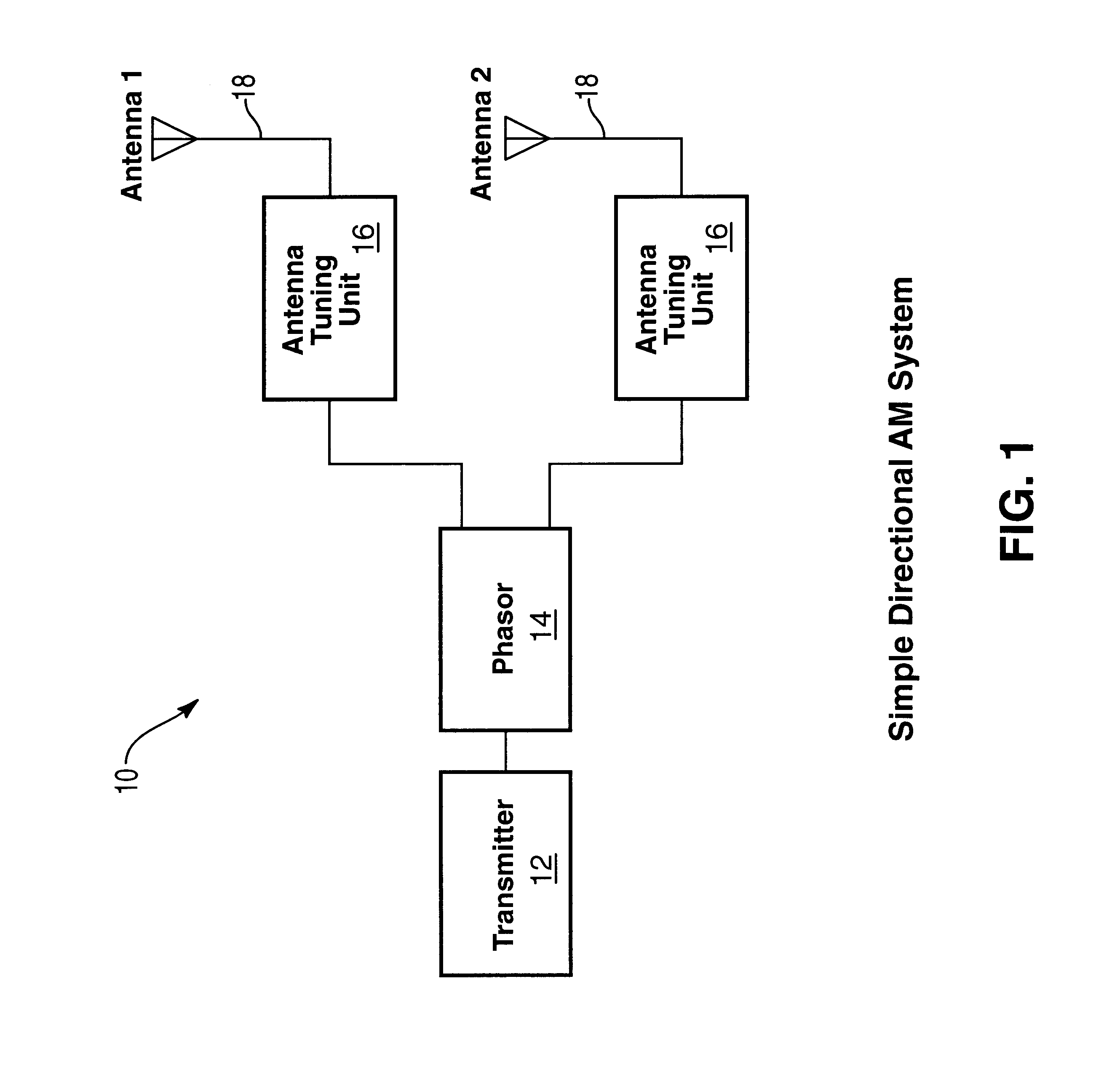
[0026]Present directional AM broadcast systems employ a system of power division and envelope delay to create the desired directional pattern. FIG. 1 illustrates a block diagram of a simple directional AM system 10 that may be mounted on a reference tower. The system 10 includes a transmitter 12 that may be comprised of a number of additional sub-components. The transmitt...


PUM


Abstract

A transmission system delays a carrier wave and program audio in the digital domain. The carrier wave and the program audio are converted to analog and the carrier wave is modulated by the program audio. The system includes a master oscillator that generates a digital carrier wave. The digital carrier wave is transmitted to a delay stage that delays the digital carrier wave by a certain delay value. The system further receives an analog or digital signal that is representative of programming. If an analog signal is received, the signal is transmitted to an analog-to-digital converter where it is converted to digital audio. The digital audio is then transmitted to a delay stage that delays the digital audio by the same delay value. The digital carrier wave and the digital audio are converted to an analog carrier wave and analog audio respectively. A modulator modulates the analog carrier wave by the analog audio and sends the amplitude modulated carrier wave to a power amplifier. After power amplification, amplitude modulated carrier wave is broadcast by a conventional antenna. The delay of the carrier wave and the program audio are controlled by a processor. The processor may also control the output power of respective power amplifiers.

Description

RELATED APPLICATIONS[0001]The present application claims priority from U.S. patent application Ser. No. 60 / 175,071, entitled “Directional Antenna System and Digital Exciter / Phasor / Transmitter,” filed Jan. 7, 2000, which is hereby incorporated by reference.BACKGROUND OF THE INVENTION[0002]1. The Field of the Invention[0003]The present invention is related to radio transmission equipment, and more specifically to directional antenna systems featuring phase shifting.[0004]2. Technical Background[0005]AM and FM radio broadcasts are extremely popular for their transmission of audio programs. AM and FM radio has been employed for several decades and can be found world wide. Radio receivers have numerous embodiments including various portable receivers to be manually carried as well as being incorporated into vehicles. AM radio has a disadvantage in that it does not provide high fidelity as does FM radio. As such, AM radio has not enjoyed quite the popularity that FM radio has for musical ...

Claims


Application Information

Patent Timeline
Patent Type & Authority Patents(United States)
IPC IPC(8): H03C5/00H01Q3/38H04B1/04
CPCH04B1/04H01Q3/38
Inventor HIEB, MARIO
Owner HIEB MARIO
Why Eureka
Try Eureka