Die cushion device comprising a hybrid drive unit

A drive device and hybrid drive technology, applied in the field of stretch pad devices, can solve the problems of destroying the force transmission mechanism and not having overload protection performance, and achieve the effects of compact structure, small moment of inertia, and reduced structure space

Inactive Publication Date: 2009-12-02
MASCHFAB MULLER WEINGARTEN AG
View PDF3 Cites 11 Cited by
  • Summary
  • Abstract
  • Description
  • Claims
  • Application Information

AI Technical Summary

Problems solved by technology

However, such stretching pad arrangements with hybrid drives only allow a compact construction in modular form, since the two drive types are not centered on one axis
In addition, previously disclosed electrically driven stretching mat devices do not have sufficient overload protection performance compared to hydraulic stretching mats
Thus, for example, the electric drive is not able to adjust the large existing rotational speed difference when the press punch strikes the stretching pad arrangement, so that higher accelerations act on the inertia of the force transmission mechanism and can cause Destruction of the force transmission mechanism due to the resulting enormous force

Method used


Image

  • Die cushion device comprising a hybrid drive unit
  • Die cushion device comprising a hybrid drive unit
  • Die cushion device comprising a hybrid drive unit

Examples


Embodiment Construction

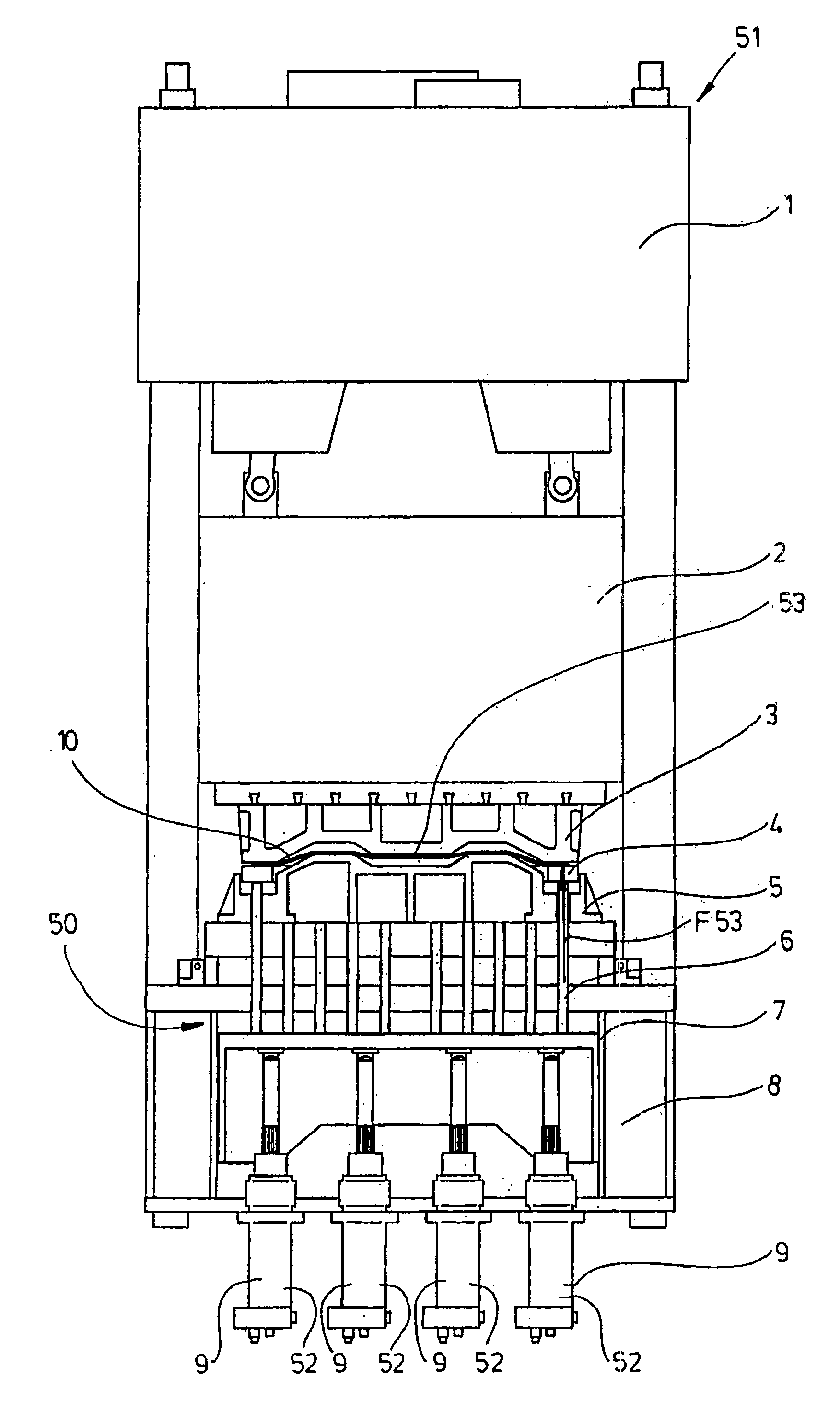
[0025] figure 1 The schematic design of a forming press 51 for stretching large-area components 10 , for example in the form of blanks 53 or sheets of synthetic material, is shown. The press has a mechanical drive 1 which moves the punch 2 together with the upper die 3 up and down. Arranged in the press table 8 is a stretching pad arrangement 50 with a hybrid drive 52 comprising a compression yoke (Druckwange) 7 and a A plurality of stretch mat modules 9 or a hybrid drive 52 . Standing on the pressing yoke 7 is a pressing bolt 6 which holds the blank carrier 4 together with the drawing workpiece 10 and acts on the drawing workpiece 10 from below with a blank holding force F53 . After placing the punch 2, the upper mold 3 is connected to the slab support 4 through the drawing workpiece 10 and pulls the slab support 4 toward the pressing bolt 6, the pressing yoke 7 and Pad modules 9 press, said tension pad modules 9 support said compression yoke 7 . Each stretching pad modu...


PUM


Abstract

The invention relates to a die cushion device (50) for a forming press (51) for generating a blank retaining force (F53) between a bottom die (5) and a top die (3). Said die cushion device (50) comprises at least one hybrid drive unit (52) which acts upon at least one blank holder (4) of the bottom die (5) and is formed by at least one first drive unit and at least one second drive unit. The first drive unit and the second drive unit form a die cushion module (9) that encompasses a part, by means of which the blank holder (4) can be moved upward and downward by at least one of the drive units. A downward pressure that can be transmitted from the top die (3) to said part and causes a descending movement can be blocked or decelerated only by the first drive unit in order to prevent the second drive unit from being overloaded, the part being disconnectable from the second drive unit during the descending movement.

Description

technical field [0001] The invention relates to a stretching pad device, which is constructed as a module by a combination of a fluid drive device and an electric drive device, and as a stretching device in a press machine, it can be used in different ways by using one or more modules. to match the component geometry. Background technique [0002] In the press, a hydraulic stretching device is used for stretching the slab, which is arranged in the press table and applies a specified force via the press platen movable in the press table and via the press rod onto the sheet support which presses the edge of the drawn workpiece towards the upper die. Complicated and large-area drawn workpieces require different force adjustments at the edge of the drawn workpiece. In DE 3807683 A1 a stretching device is known which comprises a plurality of pressure cylinders which act independently of each other and which is assigned to each pressure cylinder a compression yoke which will be ...

Claims


Application Information

Patent Timeline
Patent Type & Authority Applications(China)
IPC IPC(8): B21D24/02B21D24/10B21D24/04
CPCB21D24/02
Inventor M·米勒
Owner MASCHFAB MULLER WEINGARTEN AG
Why Eureka
Try Eureka