Wire rope flaw detector

A flaw detection device and steel wire rope technology, applied in the direction of material magnetic variable, etc., can solve the problems of reduced induced voltage, reduced SN ratio, difficult detection, etc., and achieve the effects of increased magnetic flux leakage, extended magnetic circuit length, and enhanced number of turns

Active Publication Date: 2009-12-02
MITSUBISHI ELECTRIC CORP
View PDF2 Cites 10 Cited by
  • Summary
  • Abstract
  • Description
  • Claims
  • Application Information

AI Technical Summary

Problems solved by technology

Therefore, when damage occurs inside the wire rope, the influence on the cross-sectional area of ​​the magnetic circuit is reduced, and there is no difference in magnetic permeability, so it is difficult to detect the damage.
[0009] Furthermore, in the method of Patent Document 2 (JP-A-11-230945), there is a possibility that the detection accuracy may decrease when a plurality of damaged parts are generated close to the longitudinal direction of the wire rope.
For example, in the case where a damage of the same degree occurs in each of the two specified detection intervals, since the difference in the magnetic permeability of the two detection intervals is reduced, the induced voltage generated on the detection coil is reduced, and the SN ratio is reduced.

Method used


Image

  • Wire rope flaw detector
  • Wire rope flaw detector
  • Wire rope flaw detector

Examples


Embodiment approach 1

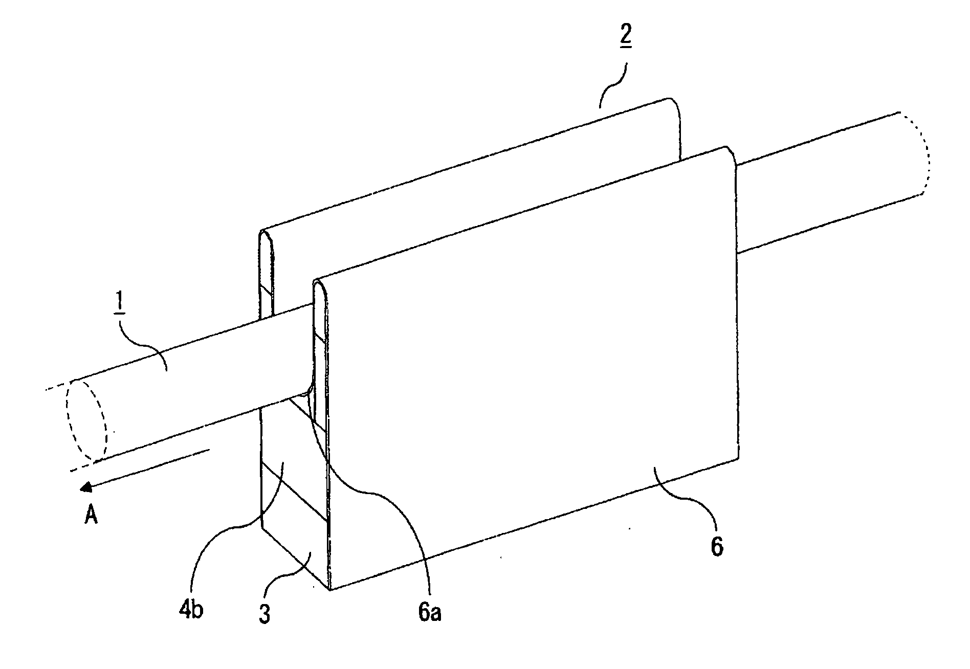
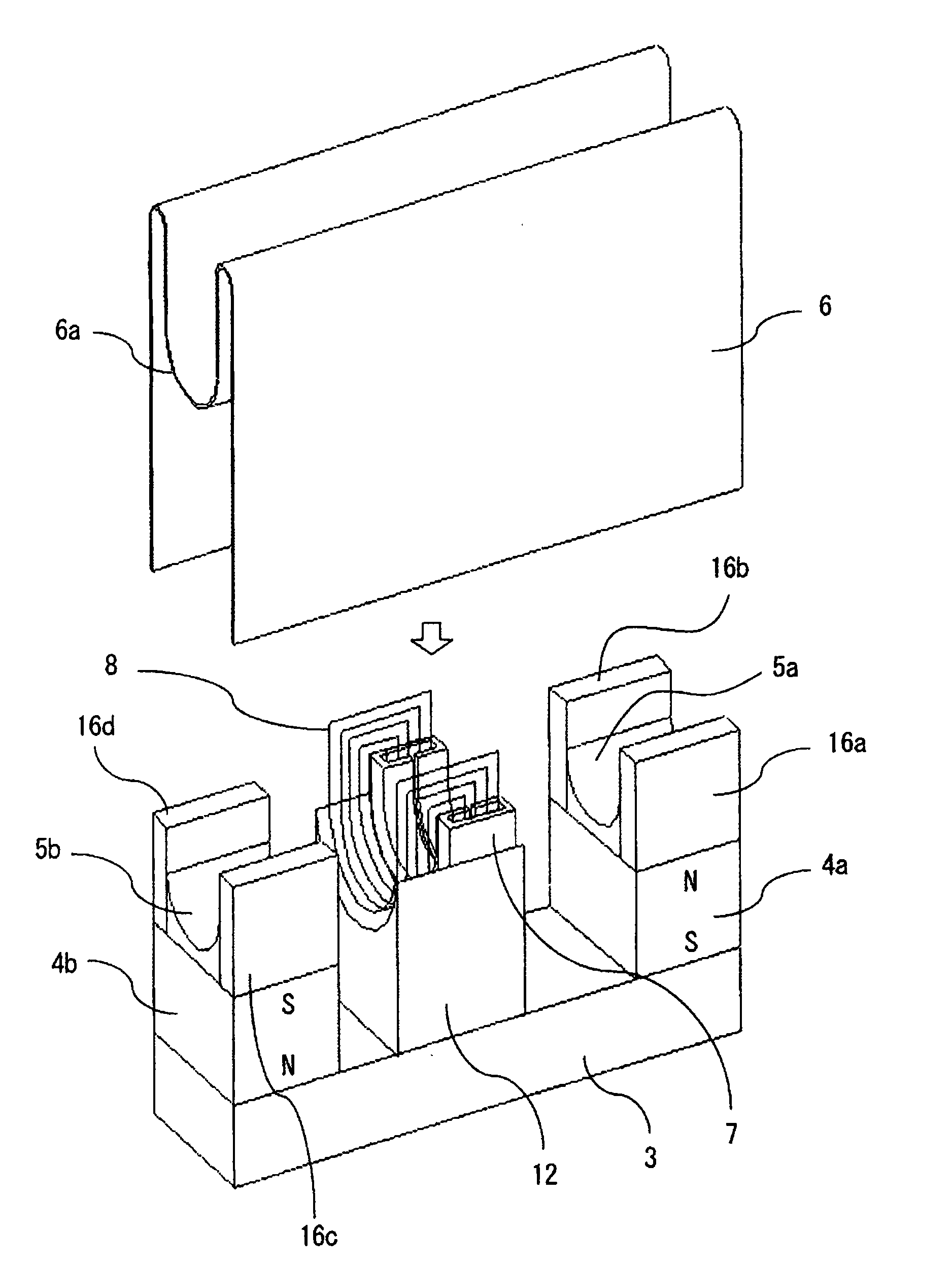
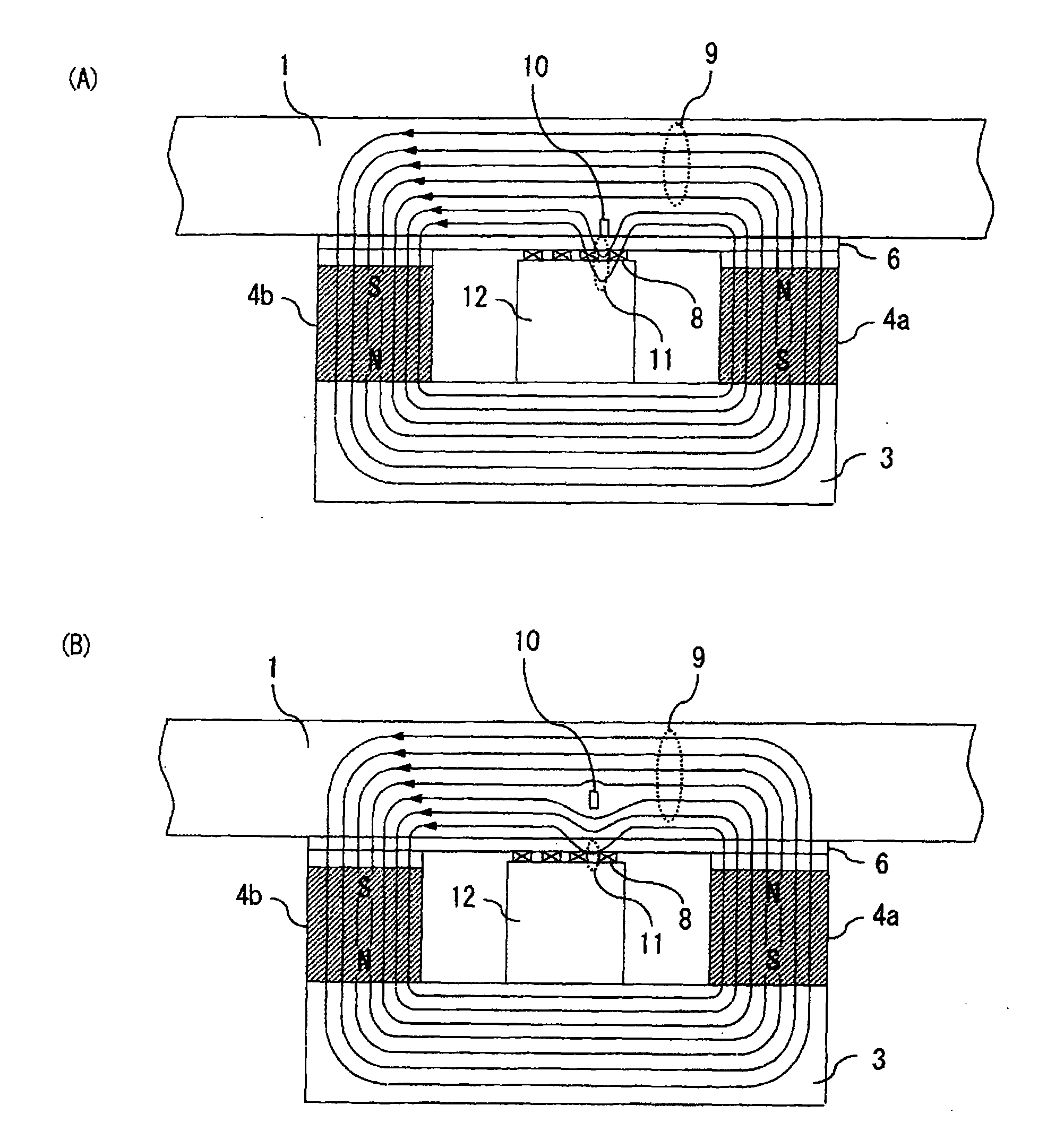
[0035] figure 1 is a perspective view showing a wire rope flaw detection device according to Embodiment 1 of the present invention, figure 2 means removed figure 1 A perspective view of the guide plate 6 of the wire rope flaw detection device. In the drawing, the wire rope flaw detection device 2 includes a guide plate 6 having a substantially U-shaped guide groove 6a through which the wire rope 1 travels (shown in A). The wire rope flaw detection device 2 of this embodiment forms a main magnetic circuit in a predetermined section in the axial direction of the traveling wire rope 1 through a magnetizer, and at the same time makes the leakage magnetic flux generated by the damaged part of the wire rope 1 go around the outside of the wire rope 1 through the magnetic circuit member 7 , the leakage magnetic flux is detected by the detection coil 8 wound around the magnetic circuit member 7 .

[0036] The magnetizer of the steel wire rope flaw detection device 2 is used to fo...

Embodiment approach 2

[0054] Figure 19 It is a perspective view showing the state when the guide plate is removed in the wire rope flaw detection device according to Embodiment 2 of the present invention. In Embodiment 1 above, as the magnetizer of the wire rope flaw detection device, the back yoke 3 made of a ferromagnetic material and a pair of excitation magnets arranged opposite to each other in polarity are shown at both ends of the back yoke 3 . Magnetizers for permanent magnets 4a, 4b. In this embodiment, if Figure 19 As shown, as the magnetizer of the wire rope flaw detection device, it is equipped with a back yoke 3 made of a ferromagnetic material, a pair of excitation electromagnets 17a that are excited in such a way that their polarities are opposite to each other at both ends of the back yoke 3, 17b. In this way, even if the permanent magnet used in the magnetizer of the first embodiment is replaced with an electromagnet, the same effect as that of the first embodiment can be obta...


PUM


Abstract

A wire rope flaw detector comprises a back yoke (3) and excitation permanent magnets (4a, 4b), which form a main magnetic path in a predetermined section of a wire rope (1) in the axial direction; a magnetic path member (7) arranged in the predetermined section to be magnetically insulated from the back yoke (3) and the permanent magnets (4a, 4b) and making the leakage flux generated from a damaged part (10) of wire rope detour to the outside of the wire rope (1); and a detection coil (8) wound around the magnetic path member (7) for detecting leakage flux. The amount of leakage flux can be increased by providing the magnetic path member (7) and since the windable area of the detection coil (8) is increased, the number of turns of detection coil can be increased.

Description

technical field [0001] The present invention relates to a wire rope flaw detection device for detecting breakage of a wire rope suspending a car of an elevator or the like and a broken wire of a single strand (hereinafter referred to as a damaged part of the wire rope). Background technique [0002] Conventionally, as a wire rope flaw detection device, there is a wire rope flaw detection device that uses a detection coil to detect leakage magnetic flux generated in a damaged portion such as a single strand break when the wire rope is magnetically saturated, and detects the damaged portion of the wire rope (for example, refer to Patent Document 1). [0003] In addition, in the past, there is also the following magnetic flaw detection device for steel wire ropes. The magnetic flaw detection device for steel wire ropes has an excitation core, an excitation coil, a power supply, and a detection coil. The excitation core has at least two magnetic poles that are relatively close to...

Claims


Application Information

Patent Timeline
Patent Type & Authority Applications(China)
IPC IPC(8): G01N27/83
CPCG01N27/83G01N27/82
Inventor 吉冈孝笹井浩之宫本佳典古泽公康唐田行庸
Owner MITSUBISHI ELECTRIC CORP
Why Eureka
Try Eureka