
Integrated self-reinforced and compact type one-time surface heat exchanging plate and flow channel structure formed by same

A compact, heat-exchanging plate technology, applied in the direction of heat transfer modification, heat exchange equipment, lighting and heating equipment, etc., can solve the problem of strengthening heat transfer components and the surface firmness of the substrate cannot be guaranteed, self-reinforced structural heat exchanger research Insufficient, poor contact between plates, etc., to achieve the effect of eliminating processing thermal resistance, preventing dust accumulation, and expanding the heat transfer surface area

Inactive Publication Date: 2011-09-14
SOUTH CHINA UNIV OF TECH
View PDF0 Cites 0 Cited by
  • Summary
  • Abstract
  • Description
  • Claims
  • Application Information

AI Technical Summary

Problems solved by technology

Anti-dust, anti-shock, and high stable heat transfer characteristics have always been problems; plate heat exchangers have the advantages of high compactness, small pressure drop, and superior vibration resistance. The literature data show that the fluid between the plates has a large disturbance at a lower flow rate, and the research on the self-reinforcing structure heat exchanger between the plates is obviously far from sufficient
[0003] Due to various reasons such as the limitation of the volume structure, the structure of the plate heat exchanger is generally very thin, and the packaging and inlay technology are mainly used. The fatal disadvantage is that the firmness of the enhanced heat transfer component and the surface of the substrate cannot be guaranteed. Poor contact, large thermal resistance, affecting heat transfer

Method used

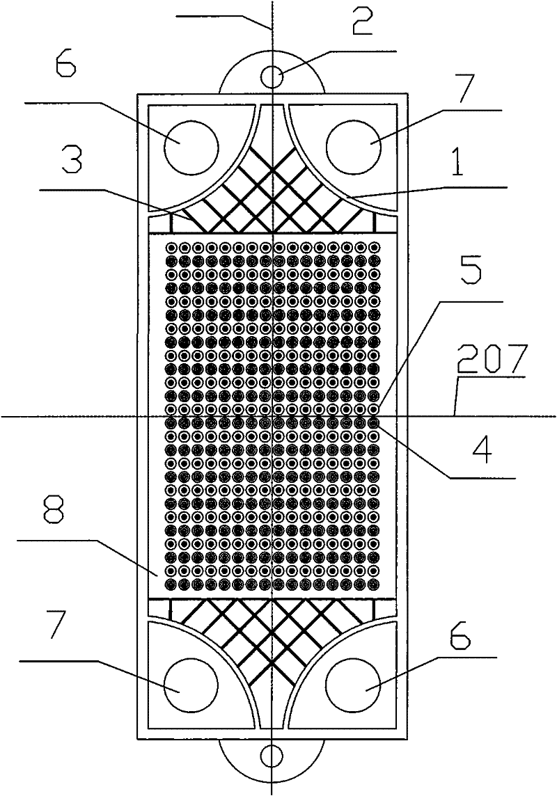
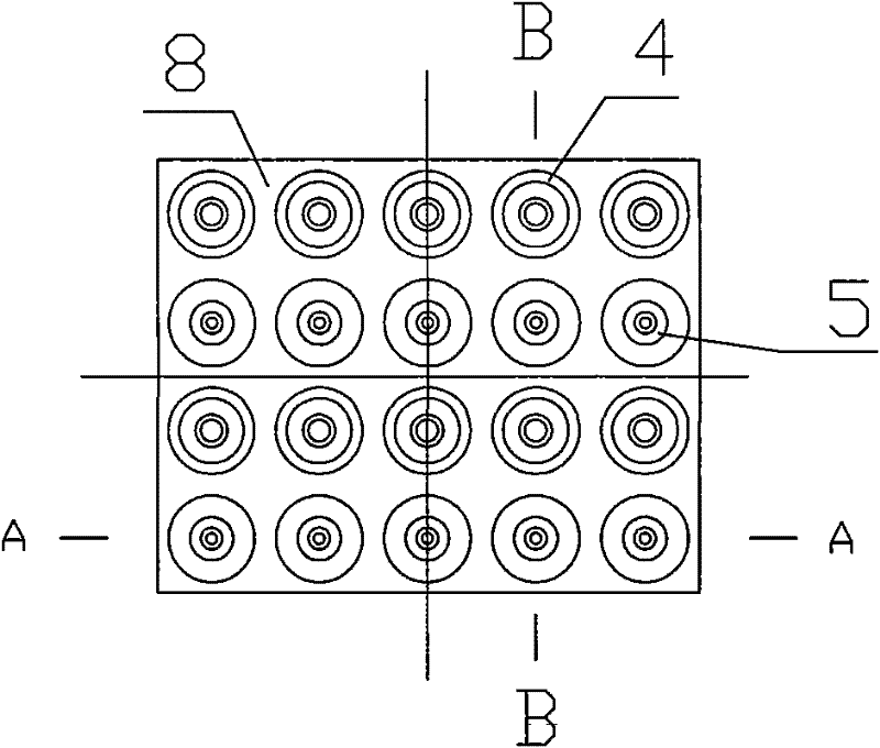

Image

  • Integrated self-reinforced and compact type one-time surface heat exchanging plate and flow channel structure formed by same
  • Integrated self-reinforced and compact type one-time surface heat exchanging plate and flow channel structure formed by same
  • Integrated self-reinforced and compact type one-time surface heat exchanging plate and flow channel structure formed by same

Examples


Embodiment Construction

[0031] The present invention will be described in further detail below in conjunction with the accompanying drawings and implementation, but the embodiments of the present invention are not limited thereto.

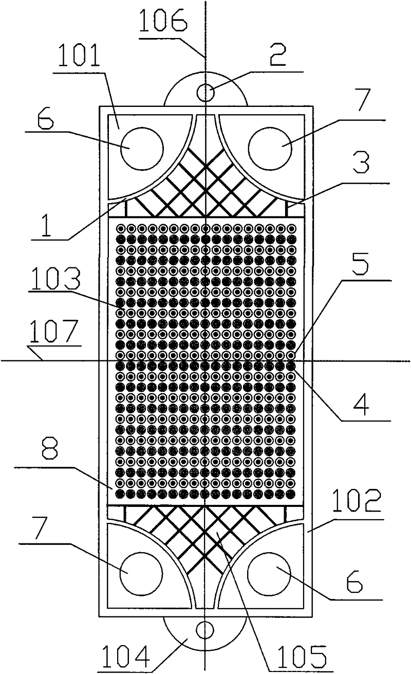
[0032] Such as figure 1 As shown, an integrated self-reinforcing compact primary surface heat exchange plate, its structure is: a through hole area 101 , an edge boss 102 , a heat exchange area 103 , a fixing area 104 and a flow guide area 105 . The edge of the rectangular heat exchange plate is provided with an edge boss 102, the thickness is 20-40mm, and the height is 1-15mm; the four corners of the rectangular heat exchange plate are provided with a through-hole area 101, and the ratio of the diameter of the through-hole to the short side of the rectangular plate The ratio is 1:3 to 1:5; a diversion area 105 is provided adjacent to the through hole area 101, and a semicircular boss 1 is provided between the through hole 6 and the through hole 7 and the diversion area. ...


PUM


Abstract

The invention discloses an integrated self-reinforced and compact type one-time surface heat exchanging plate and a flow channel structure formed by same, the heat exchanging plate comprises a through-hole area, a fixing area, a stream guiding area, a marginal convex plate, and a heat exchanging area; the heat exchanging area is rectangle distributed with a concave shell and a convex shell of cone-shaped dome, the concave shell and the convex shell are distributed in rows to form a plurality of concave shell rows and convex shell rows parallel to the short sides of the rectangle, the concave shell rows and the convex shell rows are distributed on a base plate in an alternative manner, each concave shell and each convex shell respectively correspond to circular holes on the surface on which the base plate is located, the centers of the circular holes are distributed on a straight line parallel to the long sides of the rectangle, namely, all the convex shells and the concave shells are distributed in ranks. The flow channel is composed by overlaying of at least two heat exchanging plates. The heat exchanging plate of the invention has high compactness and small volume, can save metal consumption, and greatly improves heat transmitting coefficient; the structure is streamline, thus realizing small diameter of water conservancy and reducing the mechanical loss.

Description

technical field [0001] The invention relates to a primary self-reinforcing compact heat exchange plate suitable for various types of heat exchange equipment and heating equipment in military equipment, petroleum, chemical industry, refrigeration, metallurgy, energy and other industries. Background technique [0002] Energy saving, emission reduction, and consumption reduction are the basic national policies of our country. The current challenge in the heat recovery fields of military equipment, low-emission power plants, petroleum refining, industrial furnaces, heating furnaces, coal chemical industry, chemical fiber, and cement industry is to improve equipment and Efficient process flow and cost economy maximize energy efficiency. In recent years, it has developed rapidly and is widely used in industry. At present, among various plate heat exchange equipment and heating equipment, there are mainly brazed plate heat exchangers, composite corrugated plate bundle heat exchang...

Claims


Application Information

Patent Timeline
Patent Type & Authority Patents(China)
IPC IPC(8): F28F3/00F28F3/08F28F3/04F28F13/02
Inventor 李静刘建勇樊栓狮郎雪梅罗东晓
Owner SOUTH CHINA UNIV OF TECH
Learn More