
Silicon wafer packaging structure and preparation method thereof

A technology of packaging structure and silicon wafer, which is used in semiconductor/solid-state device manufacturing, electrical components, and electrical solid-state devices. /O pitch, large bump area, effect of increasing reliability

Pending Publication Date: 2019-05-07
JIANGSU UNION SEMICON
View PDF8 Cites 0 Cited by
  • Summary
  • Abstract
  • Description
  • Claims
  • Application Information

AI Technical Summary

Problems solved by technology

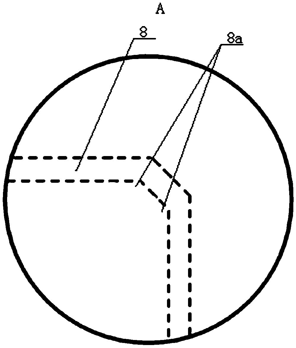
[0004] At present, the packaging structure of traditional silicon chips cannot rearrange the solder joints to any reasonable position of the chip, and the design of the chip is not flexible enough; the traditional metal wiring layer adopts right-angled corners, and chemical etching is used to remove the redundant metal areas to form metal lines. , the etchant accumulation is prone to occur at the corners of the circuit, which leads to over-etching of the metal at the bottom of the corners and reduces the reliability of the IC; the stress between the substrate and the components is large, and the components are not reliable enough

Method used


Image

  • Silicon wafer packaging structure and preparation method thereof
  • Silicon wafer packaging structure and preparation method thereof
  • Silicon wafer packaging structure and preparation method thereof

Examples


Embodiment Construction

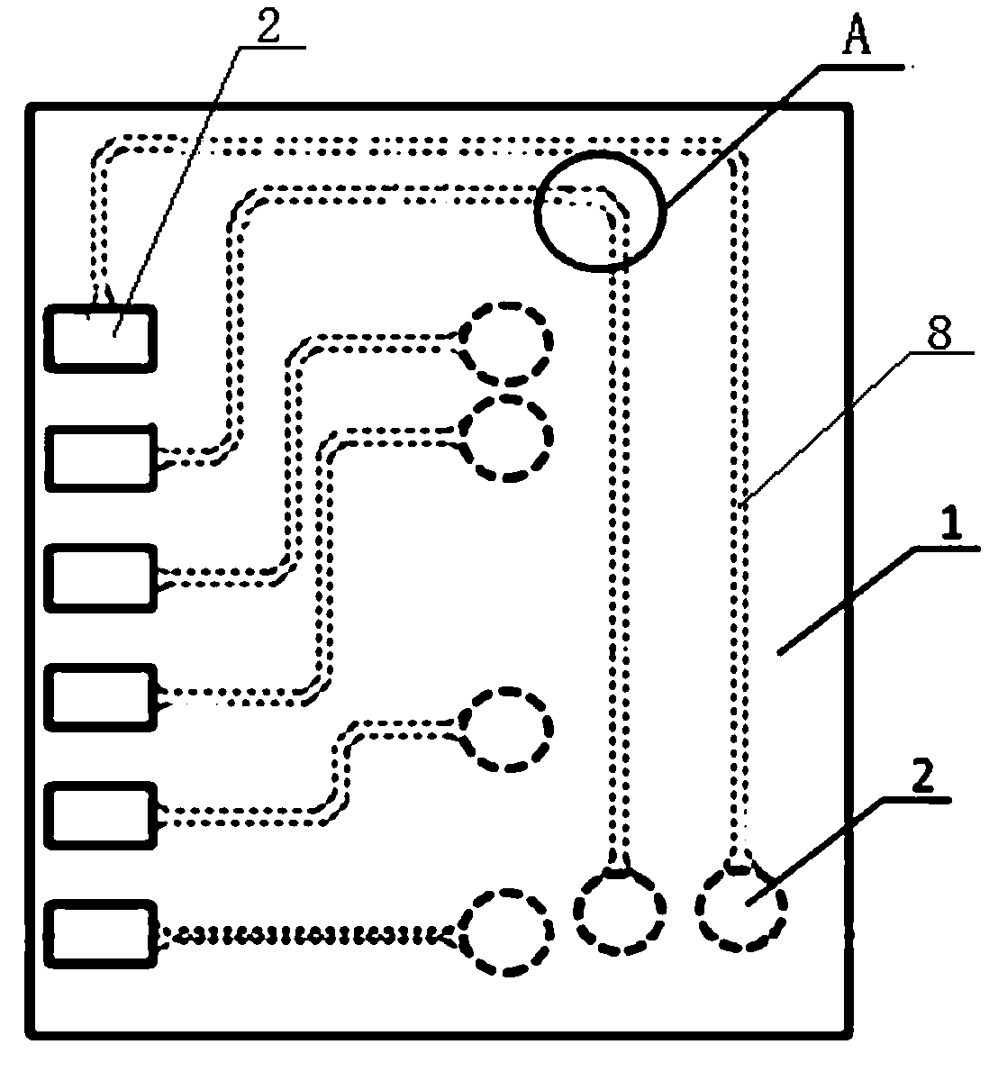
[0039] like Figure 1-13 As shown, it is a silicon chip packaging structure, including a silicon chip 1, a number of aluminum pads 2 are distributed on the surface of the silicon chip 1, and a silicon chip protective layer 3 is also covered on the silicon chip 1 and the aluminum pad 2. The thickness of the layer 3 is greater than the thickness of the aluminum pad 2, and a number of aluminum pad grooves 2a are provided on the silicon wafer protection layer 3 corresponding to each aluminum pad 2. It is also covered with a first insulating protective layer 4 made of polyimide. The lower side of the first insulating protective layer 4 is integrally provided with a lower protrusion 4a embedded in the aluminum pad groove 2a. The first insulating protective layer 4 is located on the lower side. A window slot 4b is provided above the protrusion 4a, and the window slot 4b is located above the aluminum pad 2, and an adhesive conductive layer 5 is provided above the first insulating prot...


PUM


Abstract

The invention discloses a silicon wafer packaging structure and a preparation method thereof in the field of semiconductor devices. The packaging structure is characterized in that a silicon wafer andaluminum pads are covered with a silicon wafer protection layer, a first insulating protection layer and an adhesive conductive layer are arranged on the silicon wafer protection layer, the upper side of the adhesive conductive layer is provided with a metal wiring layer and a second insulating protection layer, and the second insulating protection layer is provided with a windowing slot. The method comprises the steps of forming the first insulating protection layer on the silicon wafer protection layer; carrying out exposure and development on the part requiring the formation of circuits ofa metal wiring layer so as to expose part of metal welding points and cover the adhesive conductive layer, removing the redundant metal area to form the metal wiring layer; and finally covering the silicon wafer with the second insulating protection layer, carrying out exposure and development on the parts requiring the formation of new welding points so as to expose the metal wiring layer, namely, the new welding point area. According the invention, the welding points can be rearranged to reasonable positions of the chip, the design of the chip is more flexible, a problem of over etching ofcorner lines is solved, and the reliability of the IC chip is improved.

Description

technical field [0001] The invention belongs to the field of semiconductor devices, in particular to a silicon wafer packaging structure and a preparation method thereof. Background technique [0002] In the prior art, an integrated circuit device usually includes an IC chip or a bare chip housed in a package. The IC chip typically includes circuitry fabricated from photolithographically patterned conductive and insulating materials on a thin wafer of semiconductors using known fabrication techniques. The package supports and protects the IC chip and provides electrical connections between the circuitry and an external circuit board. For example, some known package types are used to accommodate IC chips, such as ball grid arrays (ball grid array, BGA), pin grid arrays (pin grid arrays, PGA), plastic leaded chip carriers (plastic led chip carrier, PLCC ), plastic quadflat pack, and others. [0003] Packaging refers to connecting the circuit pins on the silicon chip to exte...

Claims


Application Information

Patent Timeline
Patent Type & Authority Applications(China)
IPC IPC(8): H01L23/498H01L21/48
CPCH01L2224/05H01L2224/023H01L2924/0001
Inventor 孙晓鹏李雨李伟
Owner JIANGSU UNION SEMICON
Learn More